Category Archives: Raspberry Pi

PiDuino Adventures

At the weekend I took a 90 mile road trip north to Cambridge for the latest CamJam. As always lots to see and do, along with several purveyors of Pi related goodies, which may have been my wallets down fall.  Amongst my stash of swag is a PiDuino from the SKPang stall, at £10 down from £18 it was rude not to!

The PiDuino is an add-on board to connect an Atmega328 to a Raspberry Pi via SPI and serial.  The SPI is used to program the chip with your Arduino code and the serial (which can be disconnected) is there for communications between the devices.
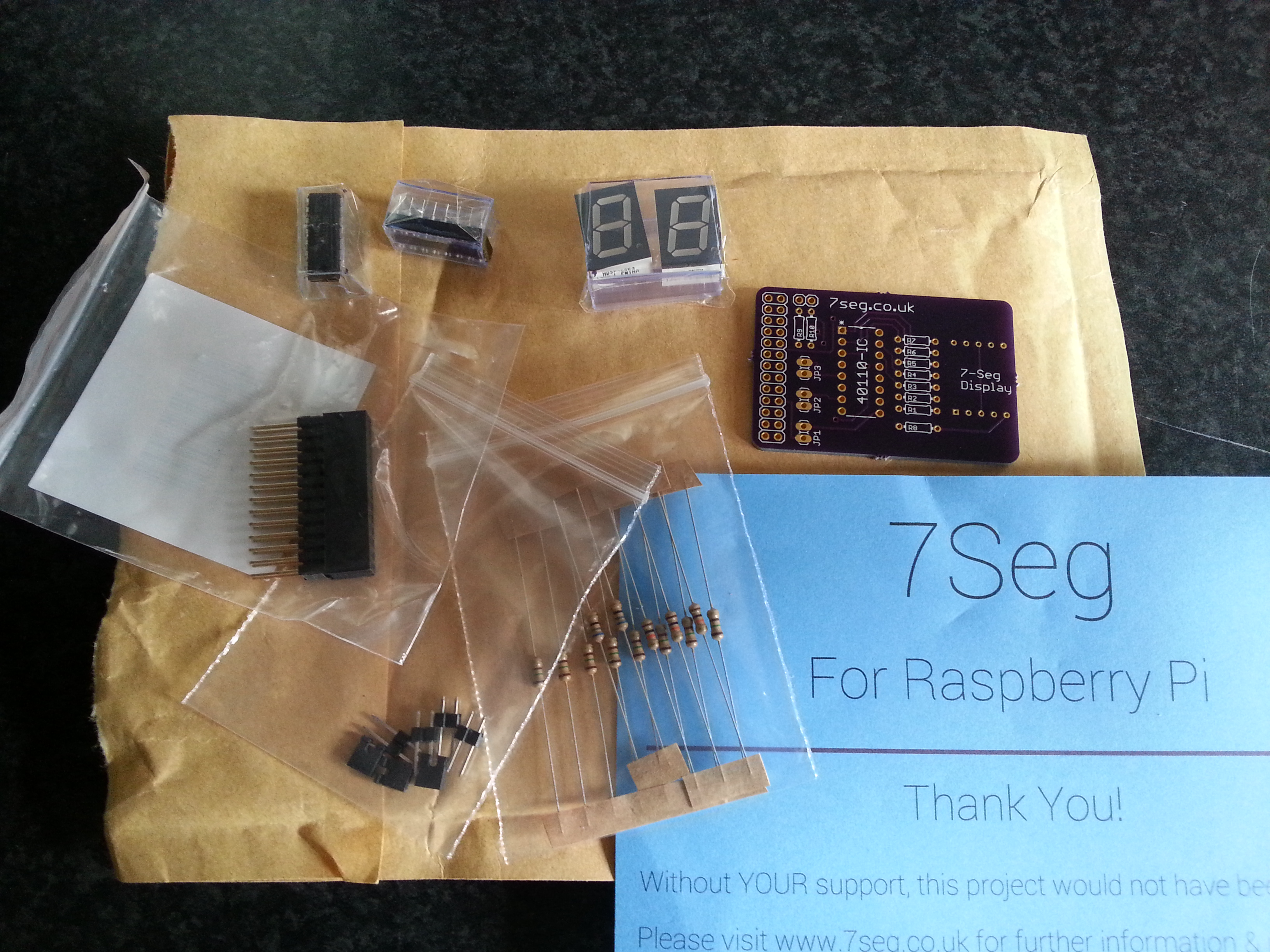
PiDuino

A PiDuino

At the CamJam in July I had been shown an early version by David (whaleygeek) Whale who has provided not only software support for the Arduino code, but also a Python library to load the compiled firmware onto the chip at runtime (more on that later).

Soldering Iron at the Ready

The PiDuino comes in kit form so I had to get soldering first.  The instructions are nice and clear, however I have asked SKPang if they could adjust the sequence of events to start with the lower profile components first.  Starting with the jumper headers made the board unstable on the worktop.

After a couple of user errors (read twice, solder once!) the board powered up and away we went!

Getting Up and Running

The first thing I did was follow the instructions to install a modified version of avrdude from Gordon Henderson, and the Arduino IDE.  In reality you only need to do this if you plan on putting together and compiling your own firmware for the ATmega on the Pi.

Enter stage left WhaleyGeek and his Python loader.  Hats off to David on this one, I won’t go into details, just read his blog post about it.

It Lives!

Yup, it had to be done; Test_Blinky.py was run, the firmware loaded and the little red LED on the PiDuino winked at me.  It’s amazing how satisfying a flashing LED can be.

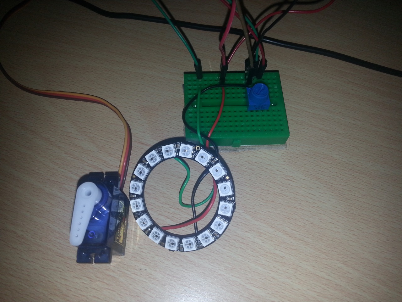
After this I downloaded Davids NeoPixel colour mixer code, wired up a 16 LED NeoPixel ring, tweaked the Python (24 NeoPixels down to 16) and ran the code.  It worked great!  The firmware that’s loaded is called CoPro and currently controls a set of NeoPixels, a servo and posts messages back when one of three analog inputs changes; all via serial comms.

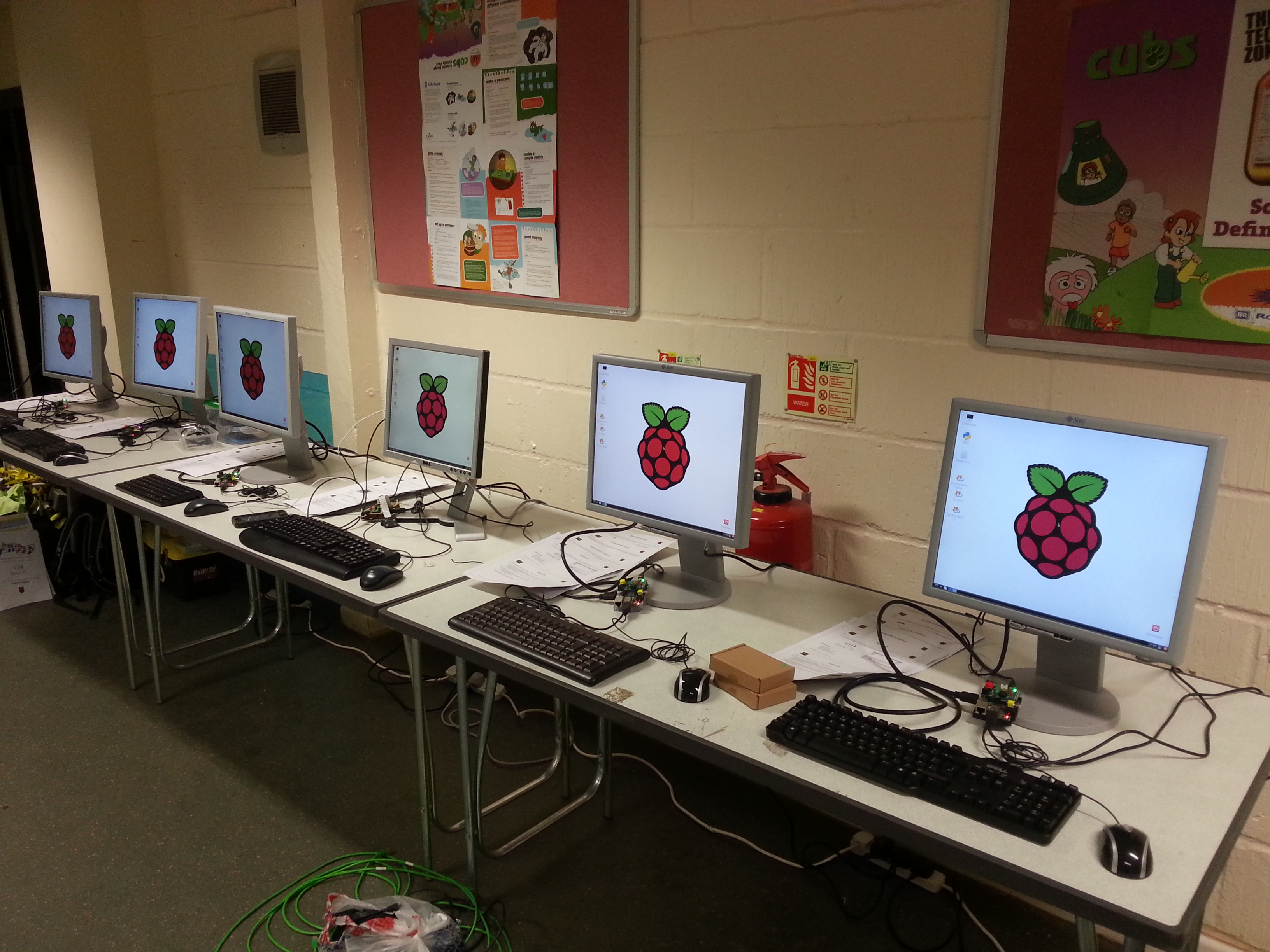
Note: As I found out the PiDuino (understandably) draws current away from your Pi.  Make sure your power supply is up to the job, the USB hub on my Dell monitor wasn’t and every time I inserted/removed/touched a wire it caused a Pi resetting brown out.  A 2A power supply stabilised things nicely.

I also attached a 10k pot (variable resistor) I had kicking around in my kit.  This allowed me to simulate one of the resistive strips on the demo program.

Time to Tinker

Once I knew it was all working was time to tinker.  Using the demo program as a base I wrote a program to change the LED position on the Neopixel ring in step with the 10k pot; as it turns, the LED moves round the ring.  Oh, and it randomly picks a colour from a pre-set list, for added blinkyness.

When I was happy with that I added a servo I had to hand, to try out the servo support in the  CoPro firmware.  Again this worked very nicely as you can see in the video below (apologies for the poor lighting, hopefully the YouTube enhancements have improved things).

There were a couple of things that tripped me up

  1. The neopixel command required a short pause after each pixel is sent
  2. Global variables are a pain in the bum
  3. The CoPro firmware pushes the current analogue value to the serial buffer when it changes.  If nothing has changed since the last read you get back no values

The first I fixed in the copro.py class provided as the pause is already present if you provide multiple pixels.  I include the tweaked copro.py and my source in this zip.  I’ve not included all the rest of the PiDuino files as these are available from David’s blog post I mentioned earlier.

Here are some close ups of the wiring – A0 = 10k pot (3.3v), D9 = servo (5v), D10 = NeoPixel ring (5v)

PiDuino Wiring Breadboard Wiring

Pi Controlled NeoPixel Ring

OK, so not 100% accurate; a Pi controlled Adafruit Trinket controlled NeoPixel ring 😀

I got the idea from seeing Dave Whale’s serial based Arduino interface with the Pi. The Trinket doesn’t have serial so I had to use something else to talk to it.

Enter I²C;  on the Trinket side I’m using the TinyWireS library, on the Pi side I’m calling smBus.writeList() with a list of the bytes I wish to send.  You’ll notice in the video there’s an extra breakout in the circuit, this is a bi-directional level converter to allow the 5v Trinket to talk to the 3.3v Pi without releasing any magic smoke.

My aim is to implement the commands in the Neopixel library however at the moment it just calls setPixelColor with the 4 values (LED, Red, Green, Blue) provided by the Pi. I have a special case of LED==0xFF which lights all LEDs the specified colour (a concept I have pinched from David).  I have included the code below in it’s current (probably hacky) state.

One problem I did find is that the Pi randomly “loses” the I²C address of the Trinket and reports it as 0x03 for a second or two.  I’m not sure if the problem is the Pi or Trinket end but it seems to be an issue with Arduinos in general.  The basis of the work around I used in my Python code can be found here. If anyone knows the reason for this I would be most grateful; it’s a horrible hack

Arduino Code

1
2
3
4
5
6
7
8
9
10
11
12
13
14
15
16
17
18
19
20
21
22
23
24
25
26
27
28
29
30
31
32
33
34
35
36
37
38
39
40
41
42
43
44
45
46
47
48
49
50
51
52
53
54
55
56
57
58
59
60
61
62
63
64
65
66
67
68
69
70
71
72
73
74
75
76
77
78
79
80
81
82
#include <TinyWireS.h>
#include <Adafruit_NeoPixel.h>
 
#define PIN 1
#define I2C_SLAVE_ADDRESS 0x04
 
// Parameter 1 = number of pixels in strip
// Parameter 2 = pin number (most are valid)
// Parameter 3 = pixel type flags, add together as needed:
//   NEO_KHZ800  800 KHz bitstream (most NeoPixel products w/WS2812 LEDs)
//   NEO_KHZ400  400 KHz (classic 'v1' (not v2) FLORA pixels, WS2811 drivers)
//   NEO_GRB     Pixels are wired for GRB bitstream (most NeoPixel products)
//   NEO_RGB     Pixels are wired for RGB bitstream (v1 FLORA pixels, not v2)
Adafruit_NeoPixel strip = Adafruit_NeoPixel(16, PIN, NEO_GRB + NEO_KHZ800);
 
// The default buffer size, Can't recall the scope of defines right now
#ifndef TWI_RX_BUFFER_SIZE
#define TWI_RX_BUFFER_SIZE ( 16 )
#endif
 
int rxIndex = 0; 
 
volatile uint8_t i2c_regs[] =
{
    0x0, // RegisterID
    0x0, // Pin
    0x1, // R
    0x0, // G 
    0x0, // B
};
const byte reg_size = sizeof(i2c_regs);
 
//Handles receiving i2c data.
void receiveEvent(uint8_t howMany)
{
    if (TinyWireS.available()){  
      if (howMany < 1)
      {   // Sanity-check
          return;
      }
      if (howMany > TWI_RX_BUFFER_SIZE)
      {   // Also insane number
          return;
      }
 
      if (howMany == 1)
      {   // This write was only to set the buffer for next read
          return;
      }
      rxIndex = 0;
      while(howMany--)
      {   //Gets i2c data. 
          i2c_regs[rxIndex] = TinyWireS.receive();
          rxIndex++;
          if (rxIndex >= reg_size){
            if (i2c_regs[1] == 0xFF) {
              for (uint8_t p=0;p<strip.numPixels();p++){
                strip.setPixelColor(p,strip.Color(i2c_regs[2], i2c_regs[3], i2c_regs[4]));
              }
            }
            else {
              strip.setPixelColor(i2c_regs[1], strip.Color(i2c_regs[2], i2c_regs[3], i2c_regs[4]));    
            }
            strip.show();
            rxIndex = 0;
          } 
      }
 
    }
}
 
void setup() {
  TinyWireS.begin(I2C_SLAVE_ADDRESS);
  TinyWireS.onReceive(receiveEvent);
 
  strip.begin();
  strip.show(); // Initialize all pixels to 'off'
}
 
void loop() {
  TinyWireS_stop_check();
}

Pi Code

1
2
3
4
5
6
7
8
9
10
11
12
13
14
15
16
17
18
19
20
21
22
23
24
25
26
27
28
29
30
31
32
33
34
35
36
37
38
39
40
41
42
43
44
45
46
47
48
49
50
51
52
53
54
55
56
57
58
import time
import smbus
import os
import subprocess
 
i2cBus = 0
i2cAddr = 0x04
bus = smbus.SMBus(i2Bus)
debug = False
 
def writeList(reg, list):
    sent = False
    attempt = 0
    while sent==False:
        if debug:
            print "I2C: Writing list to register 0x%02X:" % reg
            print list
        try:
            bus.write_i2c_block_data(i2cAddr, reg, list)
            sent = True
        except IOError:
            #a 'hack' to catch the Arduino disappearing at random intervals
            #runs i2cdetect to refresh the i2c interface, output to /dev/null so we don't see the output
            FNULL = open(os.devnull, 'w')
            retcode = subprocess.call(['i2cdetect', '-y', str(i2cBus)], stdout=FNULL, stderr=subprocess.STDOUT)
            time.sleep(0.1)
            attempt += 1
            if attempt == 10:
                raise Exception('Unable to connect via I2C')
 
def setLED(led, red, green, blue):
    bytes= [led, red, green, blue]
    writeList(0x01, bytes)
 
setLED(0xFF, 0, 0, 0)
time.sleep(0.5)
setLED(0xFF, 32, 32, 32)
time.sleep(0.5)
setLED(0xFF, 0, 0, 0)
 
try:
    while True:
        for p in range(0, 16):
            setLED(p, 32, 0, 0)
            time.sleep(0.1)
        for p in range(0, 16):
            setLED(p, 0, 32, 0)
            time.sleep(0.1)
        for p in range(0, 16):
            setLED(p, 0, 0, 32)
            time.sleep(0.1)
        for p in range(0, 16):
            setLED(p, 0, 0, 0)
            time.sleep(0.1)
except KeyboardInterrupt:
        pass
 
setLED(0xFF, 0, 0, 0)

Gilwell 24 Worksheets

So this weekend I’m running my first ever Pi session…. with 6 Pis and somewhere in the region of 3500 Explorer Scouts (14-18yo) for 24hrs! OK, so not all 3500 will visit but hopefully a few will!

2014-07-11 21.58.36

This is a lesson in how an offer of doing “a little something” with two Pis rapidly expands into a setup of 6 alongside some Arduino hacking, soldering, and amateur radio.

Below are the four worksheets I’ve cobbled together from various sources (all cited at the end of the documents). The format is not great, and I ended up printing two pages to a sheet (i.e. A5). I shall report back as to how it went.

Worksheet-Minecraft

Worksheet-PiCamera

Worksheet-SonicPi

Worksheet-PiBrella

Steady Hand / Live Wire Game & PiBrella

I’m currently writing some Pi activity packs to use at a big Scout event on Saturday. One of them uses the excellent PiBrella to allow easily accessible physical computing via the GPIO interface.

After taking the reader/coder through the basics (lights, buzzer and the big red button!) I put together an extension task to make a Steady Hand/Live Wire game. Here’s the setup and introduction

Steady Hand setup

Steady Hand description

The code they are given is shown below

1
2
3
4
5
6
7
8
9
10
11
12
13
14
15
16
17
18
19
20
21
22
23
24
25
26
27
28
29
30
31
32
33
34
35
36
37
38
39
40
41
42
43
44
45
46
47
48
import pibrella
import time
 
state = 'end'
startTime = 0
endTime = 0
touch = 0
 
while True:
 
    #start position touched
    if pibrella.input.a.read():
        if state != 'reset':
            startTime = 0
            touch = 0
            state = 'reset'
            print 'Home and reset'
 
    #copper wire touched
    elif pibrella.input.b.read():
        if state == 'started':
            print 'Touch!'
            touch += 1
            state = 'touch'
            pibrella.light.on()
 
    #end position touched
    elif pibrella.input.c.read():
        if state == 'started':
            endTime = time.time()
            state = 'end'
            print 'You made it in', endTime - startTime, 'seconds!'
            print 'You had', touch, 'touches of the wire'
 
    elif not pibrella.input.a.read():
        # we've started
        if state == 'reset':
            print 'Timer started - Good luck!'
            state = 'started'
            touch = 0
            startTime = time.time()
 
        # we've stopped touching the wire
        elif state == 'touch':
            state = 'started'
            pibrella.light.off()
 
    time.sleep(0.1)

and that’s it. If you saw me at CamJam, the one I had there was a pimped up version. It had an LCD attached to show the fastest time and lives remaining. The buzzer on the Pibrella was also used, while the LEDs counted down your three lives. But those, dear reader, are YOUR extension tasks 🙂

7 Seg for Raspberry Pi

A while back I saw a project on IndieGoGo by a teenager, Tom Garry.  The project was called 7 Seg for Raspberry Pi.  Having never backed anything like this I thought I’d give it a try, at £10 it’s not a lot to loose.

Fast forward about 6 weeks (5th May for those of you who care) and a brown jiffy bag landed on my door mat.  I love brown jiffy bags as they usually contain goodies!  This one did not disappoint.

7Seg of Raspberry Pi delivery


So what did I get for my £10

  • A well produced purple PCB
  • Several bags of components – a nice touch was extra resistors of each value
  • Two 7seg displays; one red the other green.  This is so you can choose your colour
  • A warm fuzzy feeling 🙂

When I eventually got round to soldering it up it was quite straight forward, it is also well documented on the 7seg.co.uk website.  Another week later I managed to find some time to test it!  Thankfully I managed to solder everything in the right places and it worked first time.

I ran a test python program using the Simple Counter example from the website.  I augmented it to count down as well as up by referencing pin 11 of the GPIO which controls the decrement function.  In the quick video below I repeated the for loop changing the upPin variable to downPin which references pin 11.

The build and the packaging are great but (sorry Tom, there’s a but), it’s a limited function device; i.e. it can only count from 0 to 9 and back again (unless I’ve missed something?).  The device has three jumpers that are closed (i.e. connected) and these relate to the reset count up and count down pins on the GPIO.  I suspect this has been done to allow leads to be attached to different pins on the header should the user wish to change the numbering.  The one I haven’t figured out yet is the open jumper at the top as I can’t seem to find any tracks leading to/from them.  However, I have yet to unpack the multimeter and go a hunting. [UPDATE: Tom pointed me at the schematic here]

If this were to go to a Rev 2 I would like to see the Borrow and Carry function made available from the 40110 chip. This could allow either feedback into the Pi via further GPIO pins or allow the daisy chaining of two or more boards

All in all it’s a tidy little add-on board which looks the part.  Top job Tom!