Using the built in lights is all fine, but if you happen to have a couple of LEDs floating around then we can have a look at the connectors on the device.
What’s an LED?
LED stands for Light Emitting Diode. A diode is an electrical component that only allows current to flow one direction; from positive to negative (+ to -). As a result an LED only works when connected the right way round. You can tell which is the positive and negative in two ways:
- Long leg is positive, short is negative
- On the rim of the LED, where the legs meet the plastic, there is a flat spot. This is next to the negative leg.
First things first LEDs must have a current limiting resistor. Failure to do so will, at best, 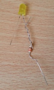 cause the LED to glow very bright, get very hot, then go black. There may even be a pop. At worse the casing will break and pieces of plastic go flying! A 330 or 470 ohm resistor should do the trick. You can buy LEDs with the resistors built in, but these are not common.
On the left is one way of adding a resistor.
Wrap one of the legs of the resistor around the long leg of the LED. Make sure that the resistor leg doesn’t make contact with the short leg. Also check that the end of the long leg isn’t in contact with the other side of the resistor; we don’t want to bridge over the resistor.
If you like you can add a drop of solder, or some tape to secure it in place.
Back to the Crumble
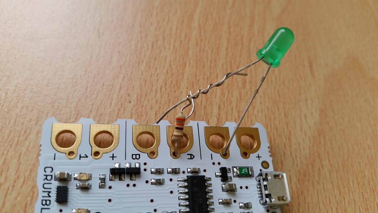 First we need to connect the LED. This can be done one of two ways; either use crocodile clips, or poke the wires through the small holes next to the connector holes.
Connect the long leg (with resistor) to A on the board, connect the short leg to the hole above (marked with a minus sign).
Now build and run the following code
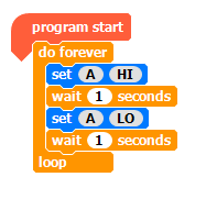
This is the same code as the Blink exercise earlier. All that’s changed is the “motor” block has been swapped for a “set” block. “HI” is short for High or ‘set the voltage as high as it will go’. It could also be though of as On. “LO” is short for Low or Off.
Now add a second LED to B (if you have one), use the negative from motor connector 1. Try working out the blocks for yourself.
(OK, if you’re stuck here is the code)
Putting it all together
In the last example I used a yellow/amber LED on purpose. With the red LED from motor 1 we have a traffic light sequence (credit to @cymplecy for pointing that out). Here’s a quick video of all three lights working in an alternating sequence.
Can you build the blocks needed to make a traffic light sequence? With another green and amber, the code could be extended for two sets of lights, like those found at a junction or cross roads.
Good afternoon. Crumble software project advice
I’ve recently bought a Crumble board and I would greatly appreciate a favour from you, if you’re willing, and knowledgeable. I am working on a project that includes the need to switch on and off a small motor for a few seconds, via Crumble software. I’ve found out how to do this using push button switches for different times and this works as required. I want to use a potentiometer to set the ON time and then it will switch OFF after the required time has elapsed. The timing range of the pot. would be from 2 to 9 seconds. What value pot. would you suggest and a log. or linear type?
The pot. would be set to the chosen position, ‘ C ‘ button pressed and released. This would switch the motor on and it would switch off after the chosen time has elapsed.
If you’re willing to do this the best way may be to email me a screen grab of the coding, or the file itself. I hope that you don’t mind my asking for your help. Thank you. I’ve recently retired from my own business making animated electro – mechanical devices for point of sale advertising displays. 555 timers were used a lot but I still ‘dabble’ with devices and would like to use more modern technology.
Kind regards, Gordon Bullock. Coventry
It should be fairly straight forward. Use a linear pot (so the resistance change is constant), read the value in and divide it to give you an approximate number between 0 and 7, then add 2 to the result to get your desired range.
In my testing the two pots had a max of 243, so dividing be 34 should give you the right scale. Below is the code
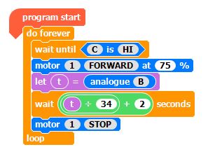
and the hardware