The CrumbleBot is a floor robot chassis from 4tronix for the Crumble. It provides a solid robotics platform with two independent motors, along with light sensors, infrared line sensors, two “sparkles” and a push switch… all on board! These inputs and output are connected to the Crumble using croc-clip connection points.
For build instructions please visit the build page
The following exercises were developed for a session I ran at a Scout event (video at the end). They give a great introduction to the functions on the CrumbleBot.
Pretty Lights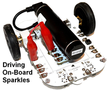
Using a crocodile lead connect D on the Crumble with LEDs on the CrumbleBot board. This will enable the Crumble to use the “Sparkle” lights on the front.
Now build the program shown below
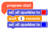
To change the colour, click the coloured square and select one from the grid that appears (doesn’t have to be the ones shown here).
Make sure the switch next to the battery is ON and press the Go button. Assuming you didn’t get an error you should see two red lights, then two blue (or the colours you chose). Then it stops, that’s not very helpful!
REMEMBER: Computers only do as they are told. It’s up to you (the programmer) to tell it the correct set of instructions for the task.
Challenge 1 – Make the lights change continuously (hint: “Do”)
Challenge 2 – Make the lights alternate
Digital Input (part 1)
On the CrumbleBot there is a push button switch; which can be connected and used to trigger an action. Using a croc lead connect the switch SW1 to A on the Crumble.
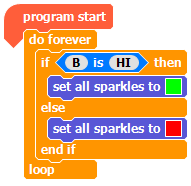
Now build the program shown below (you need the Control tab for the if…. then…. else…. block)
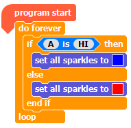
Run the program and press the push button. Ta da!
So how does this work? Pressing the button connects a high voltage (5v in this case) with input A, when the button disconnects it goes back to a low (zero) voltage. In computing this is known as a digital input; HI or 1 and LO or 0.
Using the If statement allows control of the program based on the HI or LO input.
Challenge 3 – When the button is pressed make the colour change stay for 5 seconds
So far you have (hopefully) learnt about
- Loops – repeating the same code
- Conditionals – If <some condition> Then <do something> Else <do another thing>
- Digital Input – HI/LO, 1/0, ON/OFF, TRUE/FALSE
Analog Input
On the CrumbleBot there are two Light Dependant Resistors (LDRs). They are marked LDR1 and LDR2. Using a croc leads connect LDR1 to B on the Crumble. The actual LDR is a small round component with a wiggly line on, just in front of the croc clip hole.
Now build the program shown below: (the new blocks are under the same coloured tabs at the top of the left hand panel)
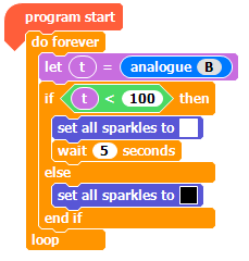
Press the Go button. The lights should go out, now cover LDR1 with a finger….. you’ve made a night light!
This code tests the value of B and, if it goes below the threshold of 50, the light comes on.
Analog inputs work by measuring the voltage received and assigning a value. The LDR works by “resisting” the flow of electricity the darker it is. In this case 255 is blindingly bright (or 5v, low resistance) and 0 is pitch black (or 0v, high resistance).
The t block is a variable. Variables are used to store values, in this case the value of the B input. If you change to the Variables tab you will notice a number beside t in the list. This is the current value of B, which you can change by putting your finger over the LDR.
Challenge 4 – Make LDR1 control sparkle 0, LDR2 control sparkle 1
Challenge 5 – Make sparkle 0 brighter the darker LDR1 gets
- Hint 1: In computing colours are made up of Red, Green, and Blue (RGB)
- Hint 2: Look in the Sparkles tab and the Operators tab
Digital Input (part 2)
The last type of inputs are two Infra Red sensors (IR) that can be used to follow a black line. Connect LINE_L to B on the Crumble
Now build the program shown below:

To test the code you’ll need a black line like the one above. You can print this one, use some black tape, or a very black felt pen/marker. Make sure the line is around 1cm thick. Put the front wheel of the bot on the line and then move the bot to the right so that the LINE_L sensor is over the black line.
The IR sensor works by sending a pulse of infra-red light (same as used in your TV remote control) and detecting if it bounces back. If it does then it’s a reflective, or white, surface. If no light returns then it’s a dark, or black, surface.
With two of these, either side of a black line, you can detect where the black line is and follow it…. but to do that we need….
Motors
Finally, the motors; what’s a robot without its wheels!
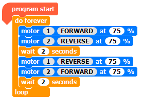
Before you press the Go button make sure you are holding it up off the desk. If you want to let it run, disconnect the USB cable that connects the CrumbleBot to the computer and give it a little room.
A quick way to stop the bot is to use the on/off switch by the battery pack. You can still program the Crumble with this off. Just remember to switch it back on for motors & sparkles!
Challenge 6 – Make the CrumbleBot move so it draws an imaginary square, then stops. It must use a loop, no duplicate commands! It must make 90 degree turns (or thereabouts)
Challenge 7 – Make the CrumbleBot follow a black line track using the IR sensors
Challenge 8 – Make the CrumbleBot follow a torch light
 If you’re a UK Scout and have completed all the challenges up to 6; congratulations you’ve just achieved requirement 4 of stage 3 of the Digital Maker Badge.
If you then carried on and completed 7 or 8 then you just levelled up and completed requirement 5 of stage 4!!
Here are a couple of examples that the Explorer Scouts managed at Gilwell 24
Hi, I love your Gilwell video. I am using the Crumblebot with primary school children and was wondering if the black line course that you created can be bought commercially.
Many thanks,
Jason
The track itself is of my own devising, I used this PDF as the source for the tiles.
Would love to see how your students get on