The blame for this little project can be firmly placed at the door of @SouthendRPiJams (aka Andy) after I signed up to be an Exhibitor at the Southend Raspberry Jam on 21st Feb. He dropped me a DM and the conversation went like this
Me:
All I have from that hardware list is the 8×8 in the shape of a UnicornHAT. Will see what time allows.
So it appears in about a week I can make an International Space Station (ISS) tracker!
The Idea
I had all sorts of ideas that could use the UnicornHAT, but they needed sensors on the AstroPiHAT that I don’t have. Here are some of the less crazy ones:
- Thermal graph (using temp sensor)
- Compass (using magnetometer)
- Pitch/roll/yaw demo (using accelerometer/gyro)
As AstroPi is going up to the ISS I started thinking how that could be incorporated.
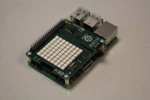
AstroPi HAT (from www.raspberrypi.org)
I follow @VirtualAstro on twitter who publishes ISS visible pass times and, from time to time, I’ll go watch the ISS fly over. In fact, I was out with my 4yo son watching “Father Christmas” going over on Christmas Eve. That was truly magical.
If you want to follow the ISS in real time there are numerous sites, one example is iss.astroviewer.net. This shows not only its position over the globe, but also an virtual “astronauts” view using the satellite view on Google Maps to provide a ground track
So the idea of an ISS tracker was born. I initially toyed with the idea of “drawing” the globe in blue and green on the grid, but it just looked like a very bad image from an 80s video game. An overlay was called for, having used one previously in the Word Clock project, but how should it look?
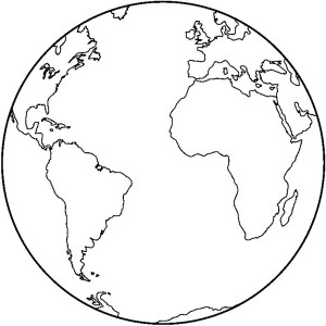
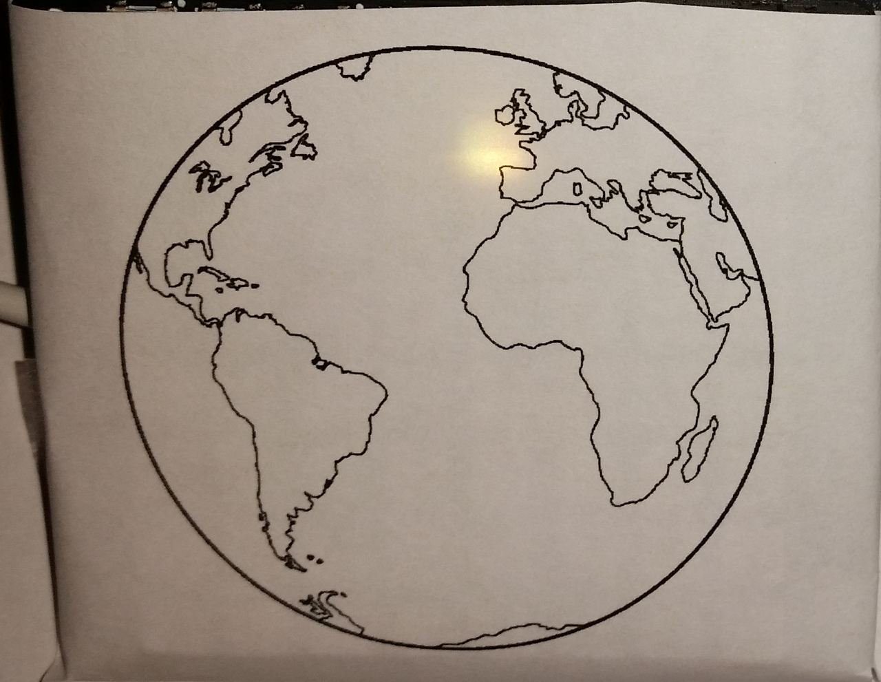
I looked at a whole world map, but with only 8 “pixels” to play with it provided very limited scope. That and the map would be a rectangle, not a square. A globe image was required, and of course it needed to have a clear image of the UK (where I live!).
In an ideal world I wanted a picture with the UK right in the middle, but my Google image search turned up the image below as the nearest to that. If anyone finds a better one let me know!
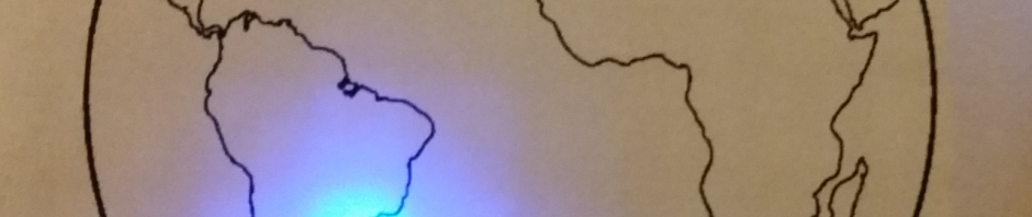
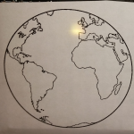
Overlay used on UnicornHAT
ISSTracker (Version 1)
Having researched trackers there are lots of sites that provide handy APIs to get the current latitude and longitude of the space station. I settled on using wheretheissis.at as this provided the most comprehensive information I could find in an API.
All the coded needed to do was pull down the JSON provided by the API then parse the data for the values it needed. Below is an extract to show you how this is done
1 2 3 4 5 6 7 8 9 10 11 12 13 14 15 16 17 18 19 20 21 22 23 24 25 26 27 28 29 30 31 32 | def getJSON(): try: jsonFeed = urllib2.urlopen(feed_url) feedData = jsonFeed.read() #print feedData jsonFeed.close() data = json.loads(feedData) return data except urllib2.HTTPError, e: print 'HTTPError = ' + str(e.code) except urllib2.URLError, e: print 'URLError = ' + str(e.reason) except httplib.HTTPException, e: print 'HTTPException' except Exception: import traceback print 'generic exception: ' + traceback.format_exc() return [] #use this method to retrieve from web API def parseISSDataFeed(): data = getJSON() if len(data) == 0: return [] lat = data['latitude'] lng = data['longitude'] alt = data['altitude'] return [lng, lat, alt] |
Now to display the ISS. The visible globe is essentially half of a sphere and so represents 180º in both the latitude (top/bottom or North/South) and longitude (left/right or East/West). With only 8 pixels that means each LED represents 22.5º of the Earths’ surface.
To display the location of the ISS we take the current lat/long of its position over the Earth and map that to the pixel/LED it falls into. That’s all well and good when it’s on the “visible” side of the globe in the overlay, but what to do when it goes “behind” our overlay?
Rather than make the ISS “disappear” I opted to still display it but in a different colour so it can be tracked as it reappears on the visible side of our globe. So now the LED lights up yellow for the visible side of the globe and blue when the ISS passes over the horizon to the rear of the planet.
-
- ISS Visible
-
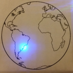
- ISS Hidden (behind)

The other thing to note is that the middle of this globe image is not the meridian (zero longitude). I estimated it is around 20º West (or -20º) so the code has an offset for this.
ISSTracker (Version 2)
Like all good projects I ended up with scope creep…. by me! I should know better really.
Change 1: Calculate the ISS location
After working with the API for a while I started reading about Two Line Element (TLE) data. The ISS (and a lot of other space objects) are highly predictable in their orbits and so can be calculated. That’s how the APIs work, and how sites like @VirtualAstro can provide a timetable of sightings.
It appears celestrak.com is the place to go for the the data which they get from NORAD (US military).
But how to use this? I found a couple of python libraries and settled on pyorbital which can be installed with
sudo pip install pyorbital
This now meant that, so long as the application had a recent version of the TLE for ISS it would know where the astronauts would be. This is ideal for taking to a Jam where connectivity might be patchy. The TLE will need refreshing every so often as manoeuvres by the ISS will change its flight path, altitude etc.
Change 2: LCD for headless use
I decided to run this headless and to do this I made use of an AdaFruit LCD addon. This allows the application to output the lat/long, altitude, azimuth and elevation without the a screen. Again, a bonus for Jams as less to transport.
I’d best explain those last two terms
- Azimuth – the compass direction of the ISS from the observation point (at the moment, Southend on Sea, Essex, UK). For those of you who have never used a compass; North = 0º, East = 90º, South = 180º, West = 270º
- Elevation – the angle of the ISS in the sky from the horizon in relation to the observation point. So a negative number means the it’s over the horizon and out of sight, a positive means it should be visible. 0º is the horizon, 90º is right over head
There’s one catch with the UnicornHAT; it doesn’t have any exposed GPIO pins, where as the LCD has an extended header (luckily). So the LCD is plugged into the GPIO and jumper wires are used to connect the UnicornHAT.
To run a UnicornHAT “off Pi” you need to wire up the following pins
- Pin 2 – 5v
- Pin 9 – Gnd
- Pin 12 – GPIO 18 / PWM
The rest can be safely ignored (source)
Video, Code, and a Note
A video of the final project in action
My source can be found on GitHub with my other projects. Have fun and let me know how you get on.
One final note. Just because the ISS is above the visible horizon (anything below 10º is not considered visible) it doesn’t mean it can be seen. The ISS doesn’t emit it’s own light (well, not enough to be seen from Earth). It can only be seen if the sun is reflecting off the space station, so the conditions to be able to see the ISS are:
- At night
- Above the visible horizon
- NOT in the Earths shadow (i.e. the Earth is not between the sun and ISS so it can reflect the light)
- Reflected light visible from where you are standing
This is why it can only be see for a week or two every few months. Head over to somewhere like www.meteorwatch.org to find the best times. At the time of writing there are numerous opportunities from now until 23rd Feb 2015, after that will be April 2015, and so on.
Pingback: ISS tracker with a Raspberry Pi and Unicorn HAT | Raspberry Pi Pod
I built a Pi based ISS tracker using an Adafruit touch LCD. It computes when ISS is visible and displays it on the screen. Here’s a picture of the screen showing a pass where ISS hits earth shadow at mid pass. If you are interested I can share the code with you.
William
Sorry, forgot link to picture: http://www.meier-phelps.com/images/20140313_225328r.jpg
Hi William,
Your project sounds great.
I’d love to build something similar (including with LEDs tracking proximity) for my little 4-year old boy so he can start becoming aware of the ISS and other satellites. I noticed that you offered to share your code. Would you mind doing so? Thanks very much. Charles
Hi Charles,
Happy to share what I have with you. Give me a few days to sort out one bug I found and then I can either send you a zip file or the link to the repo on github.
William
Many thanks for the reply, William. Will look forward to the link.
Charles
Hello William,
Just curious if you’d had a moment to look at your code and possibly github it. Thanks again for taking the time and making the effort.
Charles
Charles: https://github.com/wbphelps/ISSTracker
The current version expects an Adafruit PiTFT display, a GPS receiver on the serial port, and a USB Blinkstick. It will not run without these.
It must be connected to the ‘net to update the TLE data for the ISS.
Wow! This is quite a project. Well done. A lot more code than I expected, and I’ll probably want to mod/simplify a bit, viz., something a bit different than the BlinkStick, and perhaps another display. Regardless, this is very interesting and exceedingly generous of you to share. Thank you.
what display did you have in mind?
we should probably move this discussion to avoid hijacking this thread any more than we have – any suggestions as to where?
Hiya Carl. Have you got the graphic at the correct size for printing?
No, but if memory serves I dropped two copies of the image into Word (other word processors are available) and sized them to 5cm and 5.5cm square respectively. I think it was the 5cm version I used in the end.
Hope that helps
Thank you – that’ll do nicely! 🙂
Cool – put some pics up when you’re done. Your the first I’m aware of that’s played with this code. Let’s hope it works!