Summary
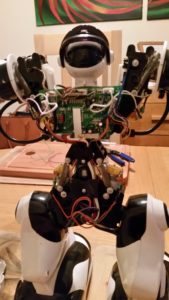
I embedded a PiZero into a Robosapien v1 and can now control it over Wifi using Python
In the Beginning
In January I tweeted this
Just picked up this fella from @RSPCA_official charity shop. Doesn't power up but for £5 let's hack! pic.twitter.com/dmhxhVvGcU
— Carl Monk (@ForToffee) January 12, 2016
I had previously seen how to hack these by using an IR transmitter and LIRC, but this meant externally mounting the hardware and I wanted this to be a more subtle hack.
It took me a while, but I finally got round to working out how to hack it. There were two possible approaches
- Tap into the Infra-red signal line and fake the remote control
- Completely replace the main circuit board and control the motors and sensors directly.
I opted for the first option as it is less of a hardware headache. Option 2 would require handling 7 motors with 4 h-bridges, along with a number of switches to detect maximum movement as well as “bumps” on feet and fingers, so that’s a project for another day!
Where to Start
There are lots of resources on how to do this with an Arduino (or similar) so these were invaluable. The IR codes can be found here, a working Arduino example is here. There are a few sites showing how to dissect a Robosapien but I found Markcra’s the most comprehensive.
For our purposes we need to identify the IR-OUT line and a ground point, the IR receiver is located in the head but this is then fed into the control board. In my initial hacking I used the male end of a M-F jumper wire and pushed it into the pins on the Head wiring connector (white for IR-OUT and grey for ground). This provided a non invasive test setup so I could work out if it was feasible to do this on a Pi (hint: it is!), but we’ll come onto that later.
-
- Defrocked!

-
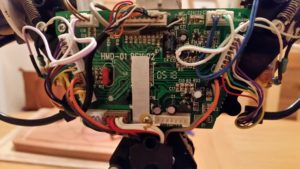
- The control board, the head connector is at the top of the PCB

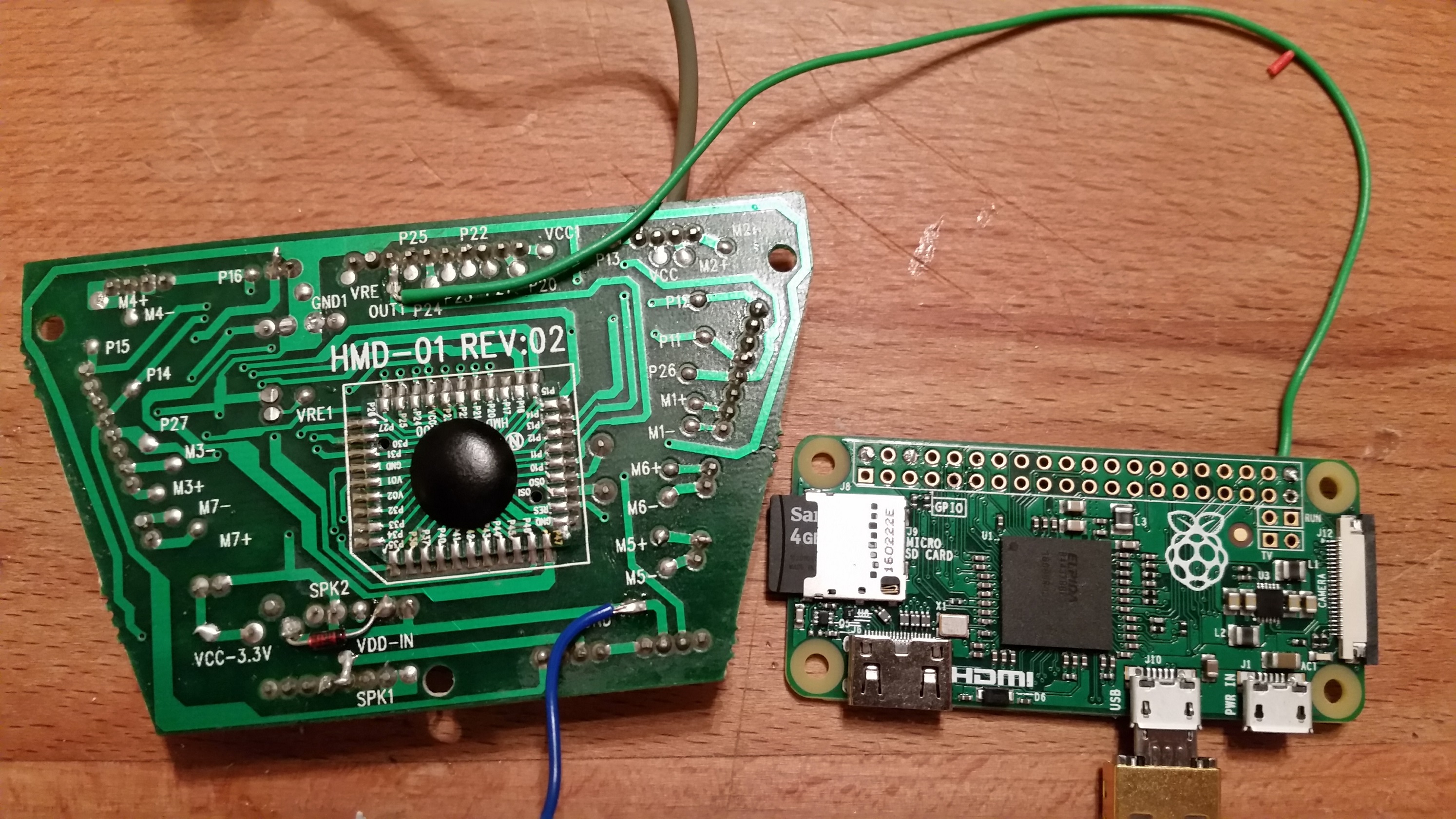
Having tested the principle I removed the control board and soldered on the connections needed.
Connecting the PiZero to the IR-OUT
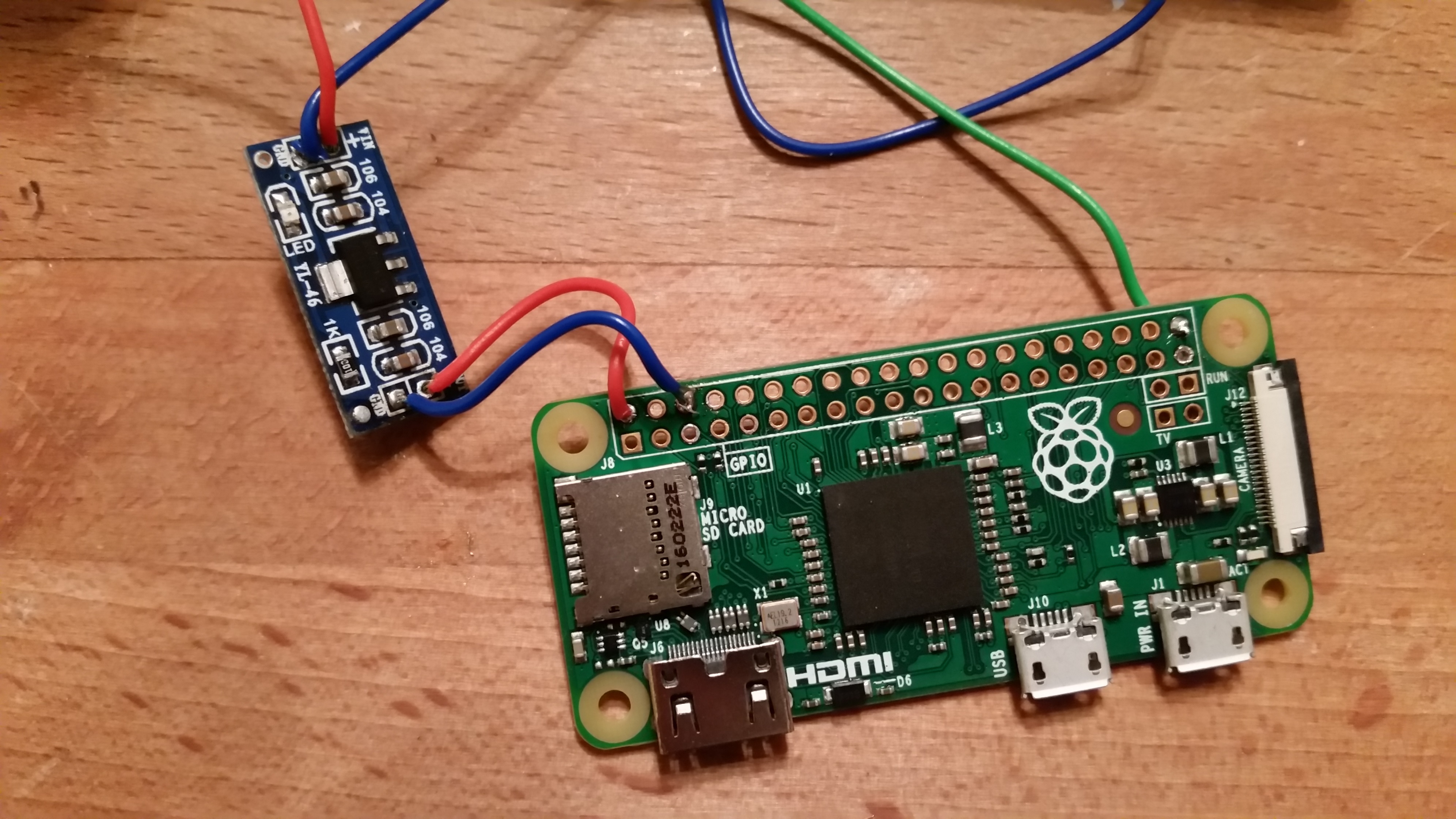
My goal was to embed the Pi, and if possible power it from the 4xD cells in the robots’ feet. These provide 6v for the motors and 3.3v for the control board and LEDs. Initially I tried to step up the 3.3v to 5v but underestimated the low power (about 100mA) the 3.3v provides. Instead I used a 6v to 5v step down (AMS1117 from eBay).
-
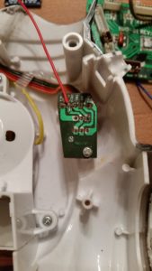
- Taking a line off the switched 6v

-

- All wired up and ready to roll
-

- Mounted in the chest cavity
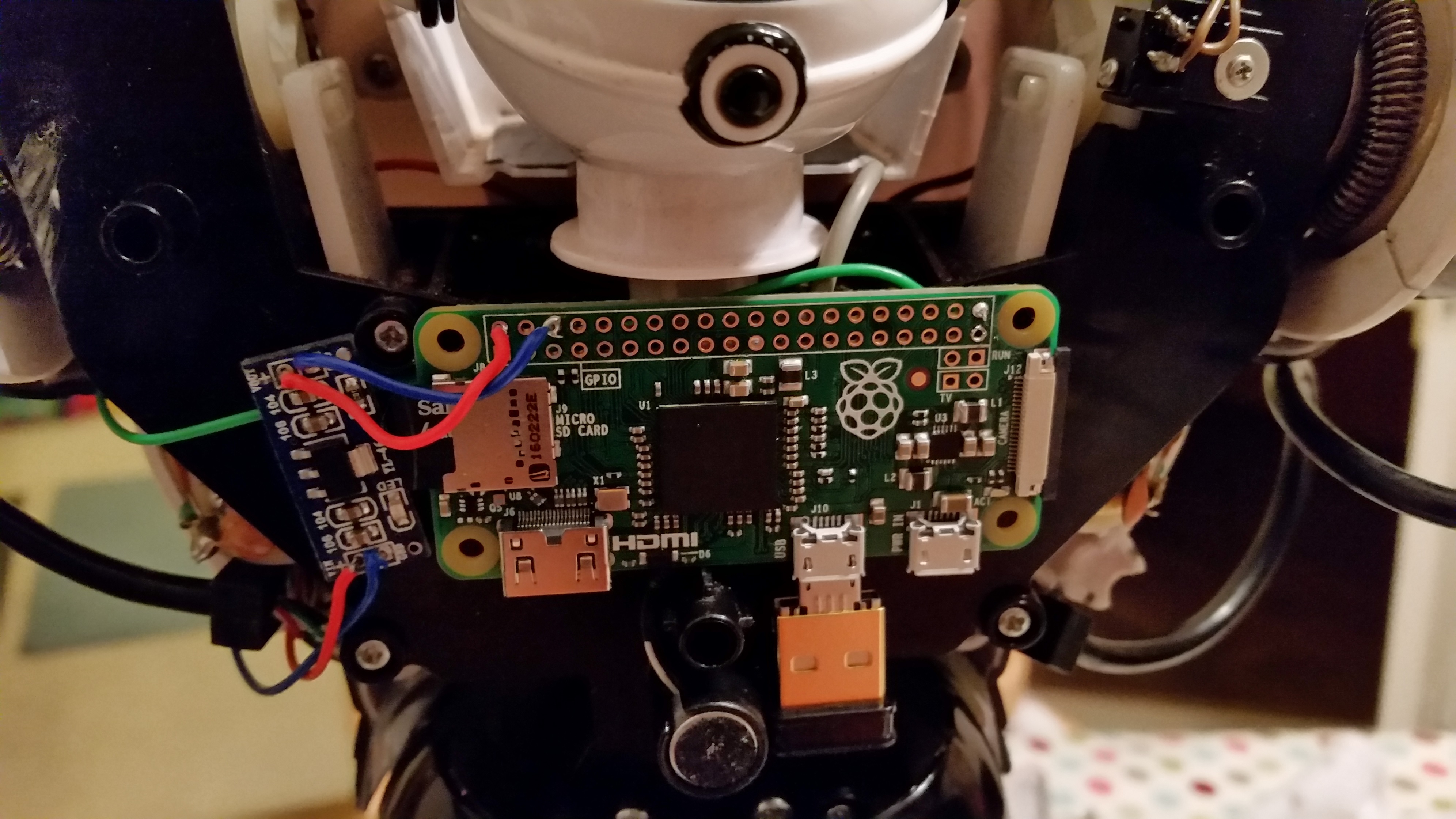
As you can see from the picture in the centre; the 5v feed is back powering the Pi via the 5v line. After a quick power and signal test I put the control board back and mounted the PiZero in the chest cavity, along with the step down power converter (above right).
Talking Infra-red
As mentioned earlier the IR codes have been well documented on the AiboHack site. The signal consists of a number of pulses denoted by high and low voltages, and these have to be performed at a certain speed for the on board processor to recognise the code being transmitted. For a Robosapien the speed is 1200Hz which gives us a cycle of every 0.833ms, and at these speeds the timing is critical. The whole code is sent as one “message” and is built as follows (from the AiboHack page)
Signal is normally high (idle, no IR).
Start: signal goes low for 8/1200 sec.
Data bits: for each of 8 data bits, space encoded signal depending on bit value
    Sends the most significant data bit first
    If the data bit is 0: signal goes high for 1/1200 sec, and low for 1/1200 sec.
    If the data bit is 1: signal goes high for 4/1200 sec, and low for 1/1200 sec.
    BTW: The first bit (msb) is always 1 (valid codes are from $80 to $FF)
When completed, signal goes high again.
To demonstrate, below is the wave form for sending the ‘right arm out’ command; which is hexadecimal 82 = decimal 130 = binary 1000 0010. Note the comment about the “most significant bit” (MSB) being sent first, the MSB is the largest binary bit which in this case represents the decimal value 128

It is very important that the signal starts at and returns to high, otherwise the control board does not realise that the transmission has finished and will be waiting for more data. You can also see that the length of a pulse can vary from 1 to 4 cycles depending on if we’re sending a 1 bit or 0 bit value.
Software
The big problem was finding a way to generate a reliable square wave. I knew it was possible as this is how Neopixels are controlled when directly connected to the Pi. The PiGPIO library has recently been added to the Raspbian repository and has functionality to generate wave forms. After some monkeying around I managed to replicate the IR signal over the GPIO wired to the control board (there may have been a happy dance, but no one saw).
To install PiGPIO
sudo apt-get update
sudo apt-get install pigpio python-pigpio python3-pigpio
PiGPIO runs as a daemon process in the background
sudo pigpiod
Once running, Python is able to interact with the GPIO via the PiGPIO service.
In the supporting Python library the wave_add_generic() command is used to create the necessary square waves. This takes a list of pulse() objects, which are made up of three parameters; GPIO pin to set high, pin to set low, and for how long in microseconds. The code below shows the waves used when a bit is set to 1; wf_hi and when the bit is 0; wf_lo (as shown in the graph above). For wf_hi, the first pulse turns the pin on for 4 cycles, the second turns it off for 1 cycle. For wf_lo the first pulse is for only 1 cycle. In this configuration, 0 is used as a pin as the circuit connects to ground.
CYCLE = 833
wf_hi = wave_add_generic(
    [pigpio.pulse(1<<pin, 0, 4 * CYCLE),
     pigpio.pulse(0, 1<<pin, 1 * CYCLE)])

wf_lo = wave_add_generic(
    [pigpio.pulse(1<<pin, 0, 1 * CYCLE),
     pigpio.pulse(0, 1<<pin, 1 * CYCLE)])
Then all is needed is to parse the command code being sent (i.e. 0x82) and work out which binary bits are on or off to build the necessary wave form. For this some bit shifting “magic” is needed. Here’s the code
data = 0x82
for x in range(8):
  if (data & 128 != 0):
     wave.append(wf_hi)
  else:
     wave.append(wf_lo)

  data <<= 1
We know the code is 8 bits long, and we need to know about the Most Significant Bit (MSB) first. To do this we use the & operand and do a bit wise comparison with 128, which is the value of the MSB position. Then, as the loop progresses, the <<= operator shifts the bits to the left by 1.
so the first 3 iterations look like this
| 128 | 64 | 32 | 16 | 8 | 4 | 2 | 1 | hex |
| 1 | 0 | 0 | 0 | 0 | 0 | 1 | 0 | 0x82 (130) |
| 0 | 0 | 0 | 0 | 0 | 1 | 0 | 0 | 0x04 (4) |
| 0 | 0 | 0 | 0 | 1 | 0 | 0 | 0 | 0x08 (8) |
By checking the left most bit each iteration through the loop we can now build up the wave form needed for the command.
I wrapped this all up into a class and provided a function called send_code(). This allows me to pass a HEX value to function and let the class sort out the waves needed. For example, to rotate the right wrist out and in again.
rs.send_code(0x82)
rs.send_code(0x85)
The full code can be found on my Github – Have a look at the test script to see how it all works
Next Steps
I have already embedded the camera module, now that the Pi Zero has camera capabilities. I just need to tidy up the interfaces and hopefully this will be my next blog post.
EDIT: I’ve added some code to GitHub that checks Twitter for the #wakedino hashtag and make the Robosapien roar!
I would love to see how this turns out over time. I have another similar robot I started to fiddle with some time ago from Wowwee (a RoboQuad), that I bet would be a similar hack.
Can you post how you are using the camera?
OpenCV?
Jan,
At the moment I’m working on a web interface with the camera stream embedded. OpenCV would be very cool though!
Can you share source?
I willing to share OpenCV code.
For OpenCV on website (javascript) look at https://trackingjs.com/
Pingback: Dale más potencia a un robot de juguete con la Raspberry Pi Zero
Sorry if it seems obvious but what is the pinout for this project? Thanks in advance.
There’s no specific pin out as there is only one wire used for the communication so any free GPIO will do. I’m using GPIO40/BCM21 in the pictures shown. The rest is just power or ground.
Many thanks for posting this. We have found and old robosapien and my son and I have now got one up and running and he is connecting it up and programming it from a script.
That’s great – would love to see it in action
Pingback: Raspberry Pi Zero Mini PC Installed In Robosapien Robot (video) – Digital Technology News and updates
Your green control board is V2. We just followed your instructions – it works fine!
Thank you for the great job.
I have another version of the control board, which is blue and of version V1. The arrangement of the contacts are slightly different. Any idea, how to connect the cables there? If this one is unknown to you, I could send a picture,
best regards,
Johann