So let’s concentrate on the hardware first. Once the first 4 digit display is up and working the rest fall in to place easily enough.
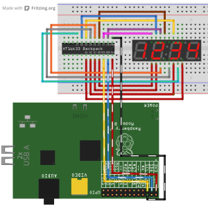
The cathodes on each of the 3 displays map to the same pins on the backpack. The displays I purchased didn’t match the datasheet on their site (I emailed them and it does now), which added an hour or so’s entertainment while I probed each of the 16 pins to work out what each one did! To give you an idea of how this maps out
| segment | a | b | c | d | e | f | g | dp |
| backpack cathode | 0 | 1 | 2 | 3 | 4 | 5 | 6 | 7 |
| 7-seg pin | 14 | 16 | 13 | 3 | 5 | 11 | 15 | 7 |
Now the cathodes are wired up we can concentrate on the anodes. As we’re only interested in the 4 digits, we can wire up as follows
| digit 1 | digit 2 | digit 3 | digit 4 | colon | |
| 7-seg pin | 1 | 2 | 6 | 8 | 4 |
| backpack anode (disp 1) | 0 | 1 | 2 | 3 | – |
| backpack anode (disp 2) | 4 | 5 | 6 | 7 | – |
| backpack anode (disp 3) | 8 | 9 | 10 | 11 | 15* |
* display 3 will show the time, so we need to be able to switch the colon on and off. Why did I choose A15, rather than A12 (next in sequence)? Why not :-). Also note that on the displays I am using the cathode for the colon is on pin 12; I wired this to pin 7 so I could turn the colon on and off by treating it like a decimal place on a normal digit.
Repeat this for the other two backpacks and you’re in business. Don’t forget to put a solder link across the address jumpers on the backpacks to give them different I2C addresses
Wired and Mounted
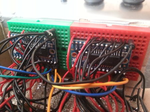
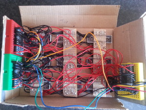
To maintain a certain amount of structure, as an aid to installing it into a box, I used stripboard to mount the displays on. I ended up with three vertical strips of board, representing a column of digits, which were then daisy chained together by the cathode wires (black). If I were to do this over I would be tempted to get stripboard wide enough to mount all the displays as this setup was still flimsy.
The other issue I had was due to the type of wire I used. The solid core was very stiff, great for holding its shape, but when you try and bend it as the box closes it has a habit of springing back, or worse popping out of the mini breadboards. Originally the breadboards were mounted on the opposite surface of the box; but due to the stiff wire they ended up mounted on the sides of the box as this won’t move when it’s closed. The end result is a much neater solution.
No Mr Fusion?
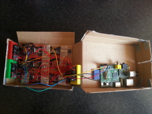
In the film, the Delorean was powered by plutonium and subsequently a fusion generator powered from garbage. The best I could manage was a 5200mAh portable battery from Tesco I have for topping up my phone while in the middle of a field. Any of these sorts of power packs will do the job, so long as they have a decent mAh and can output something in the region of 1A. The more mAh, the longer the Pi will run for. The battery could be kept inside the box, there’s enough space, but I chose to keep it outside and have a trailing cable. This meant I could power it on when I needed to and also keep an eye on the remaining charge.
I also checked with the Adafruit support guys about powering this all from the 3v3 of the Pi. Ideally the backpacks are designed to work with 4.5 – 5v so this setup is not optimal, however it does work with my model B rev1.1 (your own mileage may vary).
The Box
A quick note about the box. This was made by splicing two of the packing boxes I received from SK Pang. It was then wrapped in duct tape for that metallic look.


