A few days ago I caught wind of the #BringYourBuild competition being run by Maplin here in the UK. This was to celebrate the 11th burthday of the Arduino platform. All you needed was to submit an Arduino based project, either via social media or (preferably) in store. Continue reading →
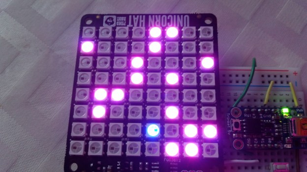
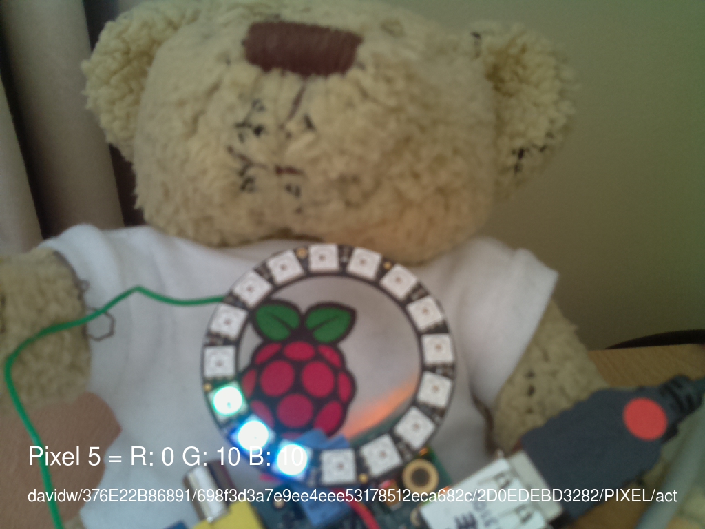
As I said in my previous post, I never actually worked with the IoT code before the workshop, so I downloaded it and combined it with my PiDuino code from earlier this week. As a result I have an Internet of Things NeoPixel ring.
At the weekend I took a 90 mile road trip north to Cambridge for the latest CamJam. As always lots to see and do, along with several purveyors of Pi related goodies, which may have been my wallets down fall. Amongst my stash of swag is a PiDuino from the SKPang stall, at £10 down from £18 it was rude not to!
The PiDuino is an add-on board to connect an Atmega328 to a Raspberry Pi via SPI and serial. The SPI is used to program the chip with your Arduino code and the serial (which can be disconnected) is there for communications between the devices.
A PiDuino
At the CamJam in July I had been shown an early version by David (whaleygeek) Whale who has provided not only software support for the Arduino code, but also a Python library to load the compiled firmware onto the chip at runtime (more on that later).
Soldering Iron at the Ready
The PiDuino comes in kit form so I had to get soldering first. The instructions are nice and clear, however I have asked SKPang if they could adjust the sequence of events to start with the lower profile components first. Starting with the jumper headers made the board unstable on the worktop.
After a couple of user errors (read twice, solder once!) the board powered up and away we went!
Getting Up and Running
The first thing I did was follow the instructions to install a modified version of avrdude from Gordon Henderson, and the Arduino IDE. In reality you only need to do this if you plan on putting together and compiling your own firmware for the ATmega on the Pi.
Enter stage left WhaleyGeek and his Python loader. Hats off to David on this one, I won’t go into details, just read his blog post about it.
It Lives!
Yup, it had to be done; Test_Blinky.py was run, the firmware loaded and the little red LED on the PiDuino winked at me. It’s amazing how satisfying a flashing LED can be.
After this I downloaded Davids NeoPixel colour mixer code, wired up a 16 LED NeoPixel ring, tweaked the Python (24 NeoPixels down to 16) and ran the code. It worked great! The firmware that’s loaded is called CoPro and currently controls a set of NeoPixels, a servo and posts messages back when one of three analog inputs changes; all via serial comms.
Note: As I found out the PiDuino (understandably) draws current away from your Pi. Make sure your power supply is up to the job, the USB hub on my Dell monitor wasn’t and every time I inserted/removed/touched a wire it caused a Pi resetting brown out. A 2A power supply stabilised things nicely.
I also attached a 10k pot (variable resistor) I had kicking around in my kit. This allowed me to simulate one of the resistive strips on the demo program.
Time to Tinker
Once I knew it was all working was time to tinker. Using the demo program as a base I wrote a program to change the LED position on the Neopixel ring in step with the 10k pot; as it turns, the LED moves round the ring. Oh, and it randomly picks a colour from a pre-set list, for added blinkyness.
When I was happy with that I added a servo I had to hand, to try out the servo support in the CoPro firmware. Again this worked very nicely as you can see in the video below (apologies for the poor lighting, hopefully the YouTube enhancements have improved things).
There were a couple of things that tripped me up
The neopixel command required a short pause after each pixel is sent
Global variables are a pain in the bum
The CoPro firmware pushes the current analogue value to the serial buffer when it changes. If nothing has changed since the last read you get back no values
The first I fixed in the copro.py class provided as the pause is already present if you provide multiple pixels. I include the tweaked copro.py and my source in this zip. I’ve not included all the rest of the PiDuino files as these are available from David’s blog post I mentioned earlier.
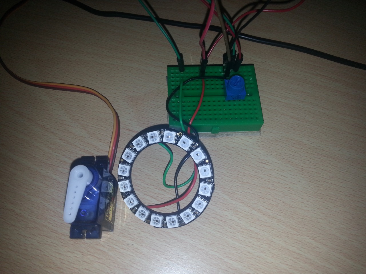
Here are some close ups of the wiring – A0 = 10k pot (3.3v), D9 = servo (5v), D10 = NeoPixel ring (5v)
OK, so not 100% accurate; a Pi controlled Adafruit Trinket controlled NeoPixel ring 😀
I got the idea from seeing Dave Whale’s serial based Arduino interface with the Pi. The Trinket doesn’t have serial so I had to use something else to talk to it.
Enter I²C; on the Trinket side I’m using the TinyWireS library, on the Pi side I’m calling smBus.writeList() with a list of the bytes I wish to send. You’ll notice in the video there’s an extra breakout in the circuit, this is a bi-directional level converter to allow the 5v Trinket to talk to the 3.3v Pi without releasing any magic smoke.
My aim is to implement the commands in the Neopixel library however at the moment it just calls setPixelColor with the 4 values (LED, Red, Green, Blue) provided by the Pi. I have a special case of LED==0xFF which lights all LEDs the specified colour (a concept I have pinched from David). I have included the code below in it’s current (probably hacky) state.
One problem I did find is that the Pi randomly “loses” the I²C address of the Trinket and reports it as 0x03 for a second or two. I’m not sure if the problem is the Pi or Trinket end but it seems to be an issue with Arduinos in general. The basis of the work around I used in my Python code can be found here. If anyone knows the reason for this I would be most grateful; it’s a horrible hack
importtimeimport smbus
importosimportsubprocess
i2cBus =0
i2cAddr =0x04
bus = smbus.SMBus(i2Bus)
debug =Falsedef writeList(reg,list):
sent =False
attempt =0while sent==False:
if debug:
print"I2C: Writing list to register 0x%02X:" % reg
printlisttry:
bus.write_i2c_block_data(i2cAddr, reg,list)
sent =TrueexceptIOError:
#a 'hack' to catch the Arduino disappearing at random intervals#runs i2cdetect to refresh the i2c interface, output to /dev/null so we don't see the output
FNULL =open(os.devnull,'w')
retcode =subprocess.call(['i2cdetect','-y',str(i2cBus)], stdout=FNULL, stderr=subprocess.STDOUT)time.sleep(0.1)
attempt +=1if attempt ==10:
raiseException('Unable to connect via I2C')def setLED(led, red, green, blue):
bytes=[led, red, green, blue]
writeList(0x01,bytes)
setLED(0xFF,0,0,0)time.sleep(0.5)
setLED(0xFF,32,32,32)time.sleep(0.5)
setLED(0xFF,0,0,0)try:
whileTrue:
for p inrange(0,16):
setLED(p,32,0,0)time.sleep(0.1)for p inrange(0,16):
setLED(p,0,32,0)time.sleep(0.1)for p inrange(0,16):
setLED(p,0,0,32)time.sleep(0.1)for p inrange(0,16):
setLED(p,0,0,0)time.sleep(0.1)exceptKeyboardInterrupt:
pass
setLED(0xFF,0,0,0)
import time
import smbus
import os
import subprocess

i2cBus = 0
i2cAddr = 0x04
bus = smbus.SMBus(i2Bus)
debug = False

def writeList(reg, list):
    sent = False
    attempt = 0
    while sent==False:
        if debug:
            print "I2C: Writing list to register 0x%02X:" % reg
            print list
        try:
            bus.write_i2c_block_data(i2cAddr, reg, list)
            sent = True
        except IOError:
            #a 'hack' to catch the Arduino disappearing at random intervals
            #runs i2cdetect to refresh the i2c interface, output to /dev/null so we don't see the output
            FNULL = open(os.devnull, 'w')
            retcode = subprocess.call(['i2cdetect', '-y', str(i2cBus)], stdout=FNULL, stderr=subprocess.STDOUT)
            time.sleep(0.1)
            attempt += 1
            if attempt == 10:
                raise Exception('Unable to connect via I2C')

def setLED(led, red, green, blue):
    bytes= [led, red, green, blue]
    writeList(0x01, bytes)

setLED(0xFF, 0, 0, 0)
time.sleep(0.5)
setLED(0xFF, 32, 32, 32)
time.sleep(0.5)
setLED(0xFF, 0, 0, 0)

try:
    while True:
        for p in range(0, 16):
            setLED(p, 32, 0, 0)
            time.sleep(0.1)
        for p in range(0, 16):
            setLED(p, 0, 32, 0)
            time.sleep(0.1)
        for p in range(0, 16):
            setLED(p, 0, 0, 32)
            time.sleep(0.1)
        for p in range(0, 16):
            setLED(p, 0, 0, 0)
            time.sleep(0.1)
except KeyboardInterrupt:
        pass

setLED(0xFF, 0, 0, 0)
I have always programmed in VB (5, 6, .NET even VBA!), I’m also starting to look at C# again after a brief dalliance 5 years ago, and of course I have a passable knowledge of Python from working with the Raspberry Pi.
Ever since picking up and playing with the Pi I have become aware of these Arduino thingies. What really peaked my interest were the wearables like GEMMA and FLORA and the work of Charlotte Godley. They’re small, uncomplicated (in theory) devices to hack about on fairly easily.
Fast forward to the beginning of the month at the July CamJam and I was enticed by The PiHut and their wares, eventually crumbling and buying an Adafruit Trinket along with a NeoPixel ring (mmmm 16 LEDs!). After getting the IDE and drivers setup (more on that later) I loaded the obligatory blink sketch, which is the Arduino equivalent of ‘hello world’.
Flushed with success (or something like that) I moved on to the NeoPixel ring, wired it up and loaded the Larson Scanner sample. It needed a couple of tweaks; namely the data pin and the number of pixels, but it worked very well.
Ultimately it was time to write my first ever bit of Arduino (or C for that matter) code, cribbing from and building on the examples I had come across thus far.
The embedded video shows alternating green and purple filling up the ring, followed by yellow and red. I was working on this while helping run Pi sessions the tech zone at Gilwell 24 so the patterns arise from the Scout brand colours and the colours of my Scout scarf respectively. My code, for what it’s worth, is below:
#include <Adafruit_NeoPixel.h>#define PIN 1// Parameter 1 = number of pixels in strip// Parameter 2 = pin number (most are valid)// Parameter 3 = pixel type flags, add together as needed:// NEO_KHZ800 800 KHz bitstream (most NeoPixel products w/WS2812 LEDs)// NEO_KHZ400 400 KHz (classic 'v1' (not v2) FLORA pixels, WS2811 drivers)// NEO_GRB Pixels are wired for GRB bitstream (most NeoPixel products)// NEO_RGB Pixels are wired for RGB bitstream (v1 FLORA pixels, not v2)
Adafruit_NeoPixel strip = Adafruit_NeoPixel(16, PIN, NEO_GRB + NEO_KHZ800);void setup(){
strip.begin();
strip.show();// Initialize all pixels to 'off'}void loop(){// Scout green and purple
spin(strip.Color(132/4,164/4,11/4),strip.Color(77/4,33/4,119/4));// BWV Explorers red and yellow
spin(strip.Color(255/4,0,0), strip.Color(255/4,255/4,0));}void spin(uint32_t c1,uint32_t c2){uint32_t c;// fill in reverse, so highest pixel number firstfor(int8_t p=strip.numPixels()-1; p>=0; p--){// set even pixels to colour 'c1', odd to 'c2'if(p%2==0){
c = c1;}else{
c = c2;}
cycle(0,p,c);}
delay(100);}void cycle(int8_t f,int8_t l,uint32_t c){for(uint8_t i=f;i<=l;i++){// clear last pixel, set current pixel
strip.setPixelColor(i-1,0);
strip.setPixelColor(i, c);
strip.show();
delay(100);}}
#include <Adafruit_NeoPixel.h>

#define PIN 1

// Parameter 1 = number of pixels in strip
// Parameter 2 = pin number (most are valid)
// Parameter 3 = pixel type flags, add together as needed:
//   NEO_KHZ800  800 KHz bitstream (most NeoPixel products w/WS2812 LEDs)
//   NEO_KHZ400  400 KHz (classic 'v1' (not v2) FLORA pixels, WS2811 drivers)
//   NEO_GRB     Pixels are wired for GRB bitstream (most NeoPixel products)
//   NEO_RGB     Pixels are wired for RGB bitstream (v1 FLORA pixels, not v2)
Adafruit_NeoPixel strip = Adafruit_NeoPixel(16, PIN, NEO_GRB + NEO_KHZ800);

void setup() {
  strip.begin();
  strip.show(); // Initialize all pixels to 'off'
}

void loop() {
  // Scout green and purple
  spin(strip.Color(132/4, 164/4, 11/4),strip.Color(77/4, 33/4, 119/4));
  // BWV Explorers red and yellow
  spin(strip.Color(255/4,0, 0), strip.Color(255/4,255/4, 0));
}

void spin(uint32_t c1, uint32_t c2){
  uint32_t c;

  // fill in reverse, so highest pixel number first
  for(int8_t p=strip.numPixels() - 1; p>=0; p--){
    // set even pixels to colour 'c1', odd to 'c2'
    if (p%2==0){
      c = c1;
    }
    else{
      c = c2;
    }
    cycle(0,p,c);
  }
  delay(100);
}

void cycle(int8_t f, int8_t l, uint32_t c){

  for(uint8_t i=f;i<=l;i++)
  {
      // clear last pixel, set current pixel
      strip.setPixelColor(i-1, 0);
      strip.setPixelColor(i, c);
      strip.show();
      delay(100);
  }
}
Things I Learnt
The USB is temperamental – After much faffing and cursing I discovered in the Adafruit FAQ about reducing the chip_erase_delay. This made things much happier on my laptop!
Updating AVRDUDE helped too – After working well on another laptop my home one refused to work again. A few Google searches later and the AdaFruit forum came to the rescue with AVRDUDE v1.15.13
Commands in C must end with ‘;’ – Obvious I know but the number of times I forgot!
For loops work differently – I’m used to a For … Until construct (i.e. For n = 0 to 15 or for n in range(0 to 16)). It took me ages to work out why my for (n= 15; p=0; p--) didn’t work correctly!
Debugging is hard – The Trinket has no serial console so you can’t see what the code is doing. To resolve one issue I ended up downloading Tiny C Complier (TCC) and creating test code to see what I was doing wrong. For reference a uint_8 of 0 minus 1 is 255 not -1 because it’s unsigned – doh!
All in all it’s been a very fun learning curve and I’m looking forward to trying out a few more AdaFruit examples. Oh wait, what’s that in the next article?