A few days back I saw this article about a Word Clock that had been built using at ATmega328P and an 8×8 LED matrix. “Cool” I thought, I have bi-colour one of those in the “toy” box, I might have a go at that.
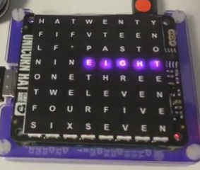
Around the same time, those pesky pirates Pimoroni were having their #yarrbooty twitter competition. I was fortunate enough to win a few rounds and decided to spend some of my booty on a Unicorn HAT and an A+. The Unicorn HAT is an 8×8 matrix of very bright RGB LEDs.
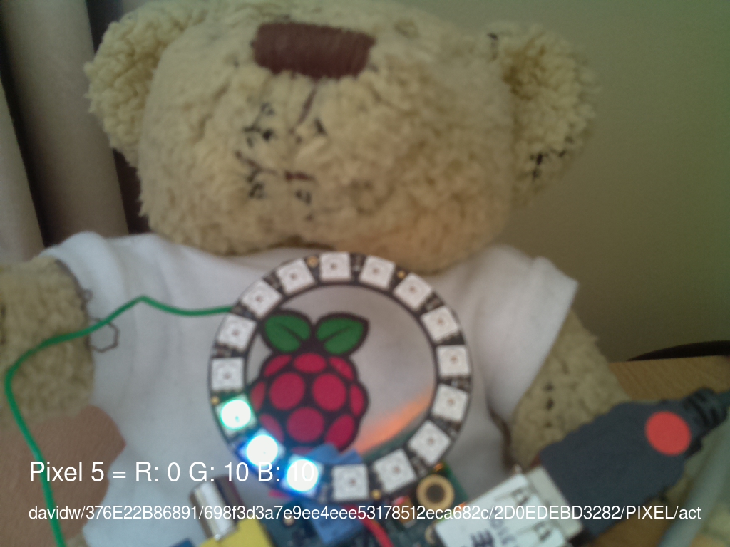
As I said in my previous post, I never actually worked with the IoT code before the workshop, so I downloaded it and combined it with my PiDuino code from earlier this week. As a result I have an Internet of Things NeoPixel ring.
At the weekend I took a 90 mile road trip north to Cambridge for the latest CamJam. As always lots to see and do, along with several purveyors of Pi related goodies, which may have been my wallets down fall. Amongst my stash of swag is a PiDuino from the SKPang stall, at £10 down from £18 it was rude not to!
The PiDuino is an add-on board to connect an Atmega328 to a Raspberry Pi via SPI and serial. The SPI is used to program the chip with your Arduino code and the serial (which can be disconnected) is there for communications between the devices.
A PiDuino
At the CamJam in July I had been shown an early version by David (whaleygeek) Whale who has provided not only software support for the Arduino code, but also a Python library to load the compiled firmware onto the chip at runtime (more on that later).
Soldering Iron at the Ready
The PiDuino comes in kit form so I had to get soldering first. The instructions are nice and clear, however I have asked SKPang if they could adjust the sequence of events to start with the lower profile components first. Starting with the jumper headers made the board unstable on the worktop.
After a couple of user errors (read twice, solder once!) the board powered up and away we went!
Getting Up and Running
The first thing I did was follow the instructions to install a modified version of avrdude from Gordon Henderson, and the Arduino IDE. In reality you only need to do this if you plan on putting together and compiling your own firmware for the ATmega on the Pi.
Enter stage left WhaleyGeek and his Python loader. Hats off to David on this one, I won’t go into details, just read his blog post about it.
It Lives!
Yup, it had to be done; Test_Blinky.py was run, the firmware loaded and the little red LED on the PiDuino winked at me. It’s amazing how satisfying a flashing LED can be.
After this I downloaded Davids NeoPixel colour mixer code, wired up a 16 LED NeoPixel ring, tweaked the Python (24 NeoPixels down to 16) and ran the code. It worked great! The firmware that’s loaded is called CoPro and currently controls a set of NeoPixels, a servo and posts messages back when one of three analog inputs changes; all via serial comms.
Note: As I found out the PiDuino (understandably) draws current away from your Pi. Make sure your power supply is up to the job, the USB hub on my Dell monitor wasn’t and every time I inserted/removed/touched a wire it caused a Pi resetting brown out. A 2A power supply stabilised things nicely.
I also attached a 10k pot (variable resistor) I had kicking around in my kit. This allowed me to simulate one of the resistive strips on the demo program.
Time to Tinker
Once I knew it was all working was time to tinker. Using the demo program as a base I wrote a program to change the LED position on the Neopixel ring in step with the 10k pot; as it turns, the LED moves round the ring. Oh, and it randomly picks a colour from a pre-set list, for added blinkyness.
When I was happy with that I added a servo I had to hand, to try out the servo support in the CoPro firmware. Again this worked very nicely as you can see in the video below (apologies for the poor lighting, hopefully the YouTube enhancements have improved things).
There were a couple of things that tripped me up
The neopixel command required a short pause after each pixel is sent
Global variables are a pain in the bum
The CoPro firmware pushes the current analogue value to the serial buffer when it changes. If nothing has changed since the last read you get back no values
The first I fixed in the copro.py class provided as the pause is already present if you provide multiple pixels. I include the tweaked copro.py and my source in this zip. I’ve not included all the rest of the PiDuino files as these are available from David’s blog post I mentioned earlier.
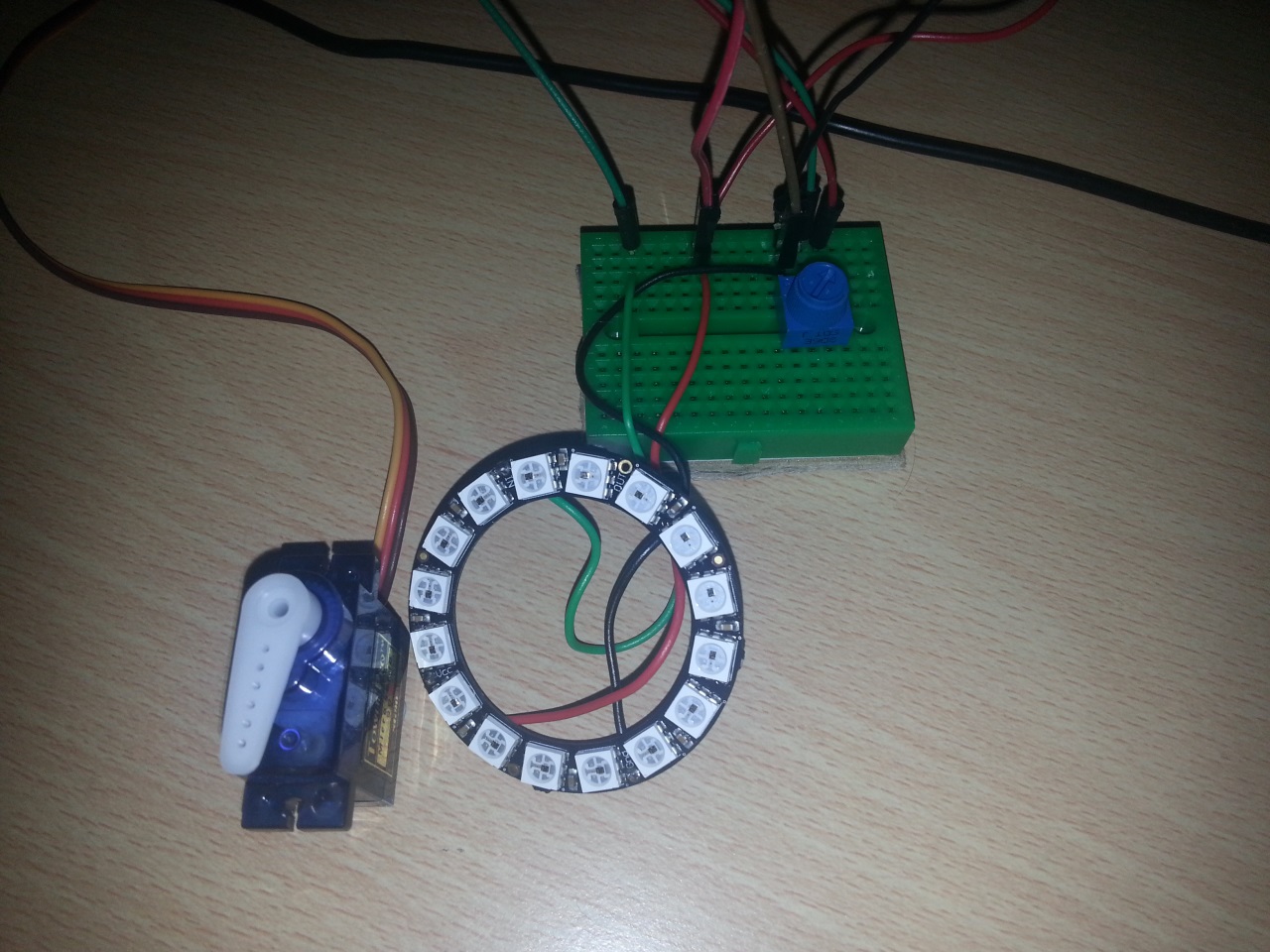
Here are some close ups of the wiring – A0 = 10k pot (3.3v), D9 = servo (5v), D10 = NeoPixel ring (5v)
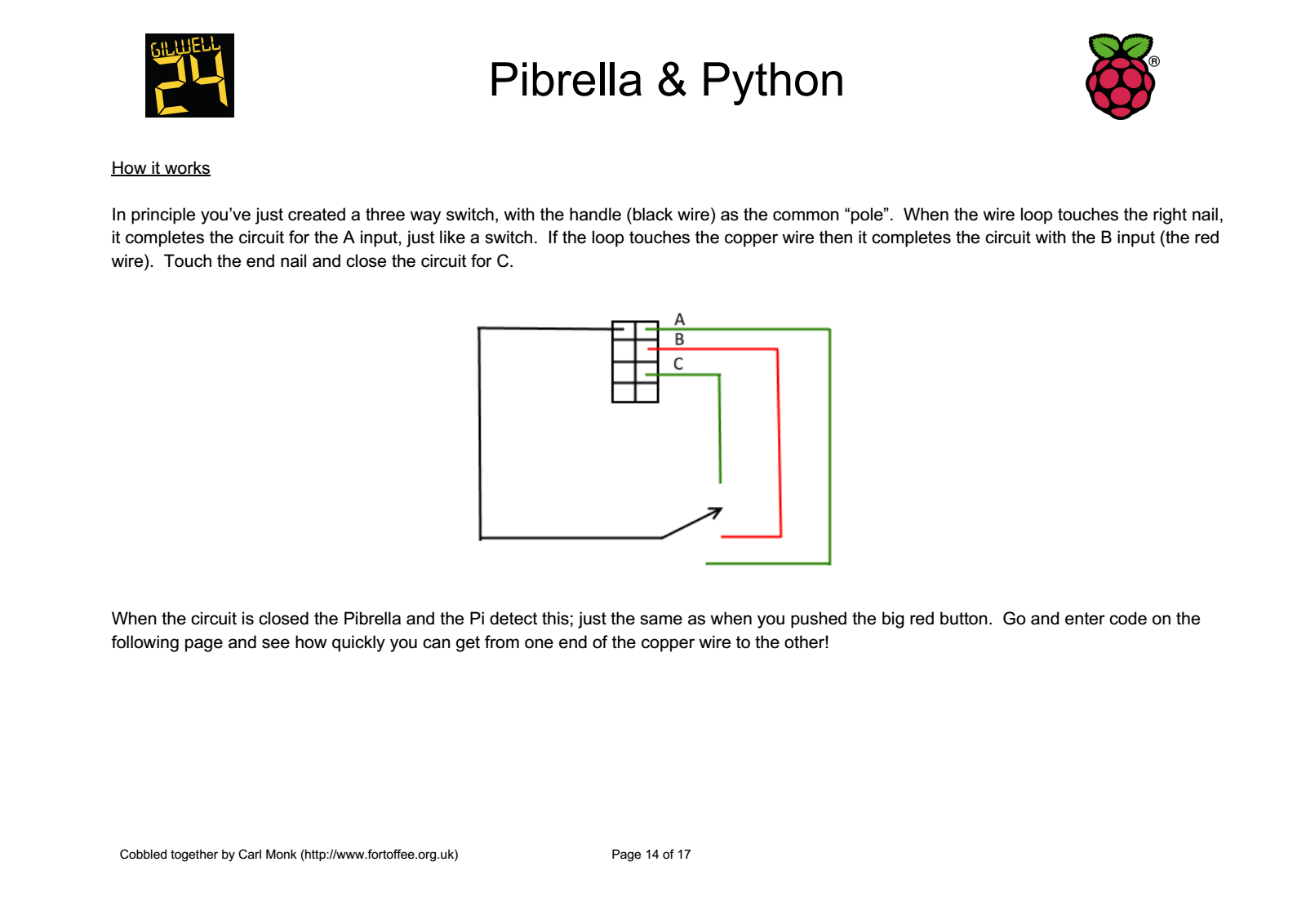
I’m currently writing some Pi activity packs to use at a big Scout event on Saturday. One of them uses the excellent PiBrella to allow easily accessible physical computing via the GPIO interface.
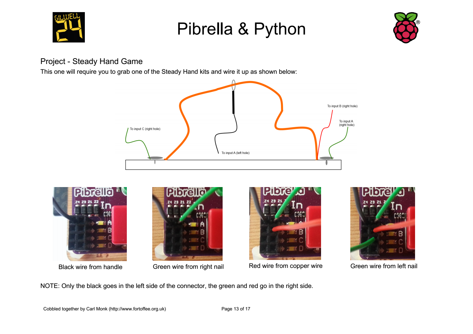
After taking the reader/coder through the basics (lights, buzzer and the big red button!) I put together an extension task to make a Steady Hand/Live Wire game. Here’s the setup and introduction
import pibrella
importtime
state ='end'
startTime =0
endTime =0
touch =0whileTrue:
#start position touchedif pibrella.input.a.read():
if state !='reset':
startTime =0
touch =0
state ='reset'print'Home and reset'#copper wire touchedelif pibrella.input.b.read():
if state =='started':
print'Touch!'
touch +=1
state ='touch'
pibrella.light.on()#end position touchedelif pibrella.input.c.read():
if state =='started':
endTime =time.time()
state ='end'print'You made it in', endTime - startTime,'seconds!'print'You had', touch,'touches of the wire'elifnot pibrella.input.a.read():
# we've startedif state =='reset':
print'Timer started - Good luck!'
state ='started'
touch =0
startTime =time.time()# we've stopped touching the wireelif state =='touch':
state ='started'
pibrella.light.off()time.sleep(0.1)
import pibrella
import time

state = 'end'
startTime = 0
endTime = 0
touch = 0

while True:

    #start position touched
    if pibrella.input.a.read():
        if state != 'reset':
            startTime = 0
            touch = 0
            state = 'reset'
            print 'Home and reset'

    #copper wire touched
    elif pibrella.input.b.read():
        if state == 'started':
            print 'Touch!'
            touch += 1
            state = 'touch'
            pibrella.light.on()

    #end position touched
    elif pibrella.input.c.read():
        if state == 'started':
            endTime = time.time()
            state = 'end'
            print 'You made it in', endTime - startTime, 'seconds!'
            print 'You had', touch, 'touches of the wire'

    elif not pibrella.input.a.read():
        # we've started
        if state == 'reset':
            print 'Timer started - Good luck!'
            state = 'started'
            touch = 0
            startTime = time.time()

        # we've stopped touching the wire
        elif state == 'touch':
            state = 'started'
            pibrella.light.off()

    time.sleep(0.1)
and that’s it. If you saw me at CamJam, the one I had there was a pimped up version. It had an LCD attached to show the fastest time and lives remaining. The buzzer on the Pibrella was also used, while the LEDs counted down your three lives. But those, dear reader, are YOUR extension tasks 🙂
One of my favourite Pibrella projects so far! Built in true maker fashion with scraps and gaffer tape! #camjampic.twitter.com/QJU8714yPI
A while back I saw a project on IndieGoGo by a teenager, Tom Garry. The project was called 7 Seg for Raspberry Pi. Having never backed anything like this I thought I’d give it a try, at £10 it’s not a lot to loose.
Fast forward about 6 weeks (5th May for those of you who care) and a brown jiffy bag landed on my door mat. I love brown jiffy bags as they usually contain goodies! This one did not disappoint.
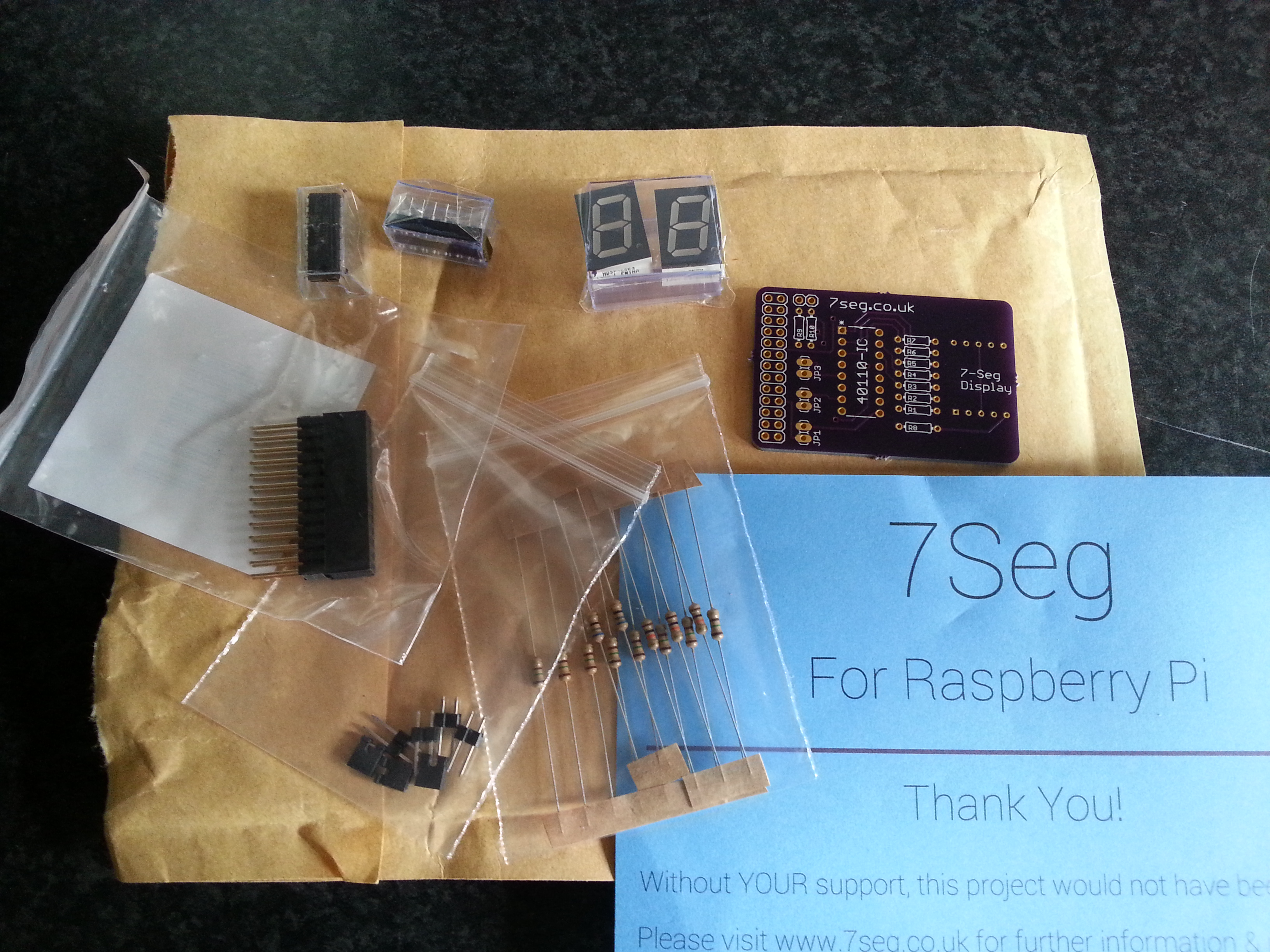
So what did I get for my £10
A well produced purple PCB
Several bags of components – a nice touch was extra resistors of each value
Two 7seg displays; one red the other green. This is so you can choose your colour
A warm fuzzy feeling 🙂
When I eventually got round to soldering it up it was quite straight forward, it is also well documented on the 7seg.co.uk website. Another week later I managed to find some time to test it! Thankfully I managed to solder everything in the right places and it worked first time.
I ran a test python program using the Simple Counter example from the website. I augmented it to count down as well as up by referencing pin 11 of the GPIO which controls the decrement function. In the quick video below I repeated the for loop changing the upPin variable to downPin which references pin 11.
The build and the packaging are great but (sorry Tom, there’s a but), it’s a limited function device; i.e. it can only count from 0 to 9 and back again (unless I’ve missed something?). The device has three jumpers that are closed (i.e. connected) and these relate to the reset count up and count down pins on the GPIO. I suspect this has been done to allow leads to be attached to different pins on the header should the user wish to change the numbering. The one I haven’t figured out yet is the open jumper at the top as I can’t seem to find any tracks leading to/from them. However, I have yet to unpack the multimeter and go a hunting. [UPDATE: Tom pointed me at the schematic here]
If this were to go to a Rev 2 I would like to see the Borrow and Carry function made available from the 40110 chip. This could allow either feedback into the Pi via further GPIO pins or allow the daisy chaining of two or more boards
All in all it’s a tidy little add-on board which looks the part. Top job Tom!