CamJam has a lot to answer for; mainly the evaporation of my evenings this past week. During the jam I helped run the “Inventing with the Internet of Things” workshop, I had no idea what it was all about as it was a last minute thing but I know enough Python and the principles of networking to bumble along. The workshop was run by David Whale in conjunction with IoTic Labs
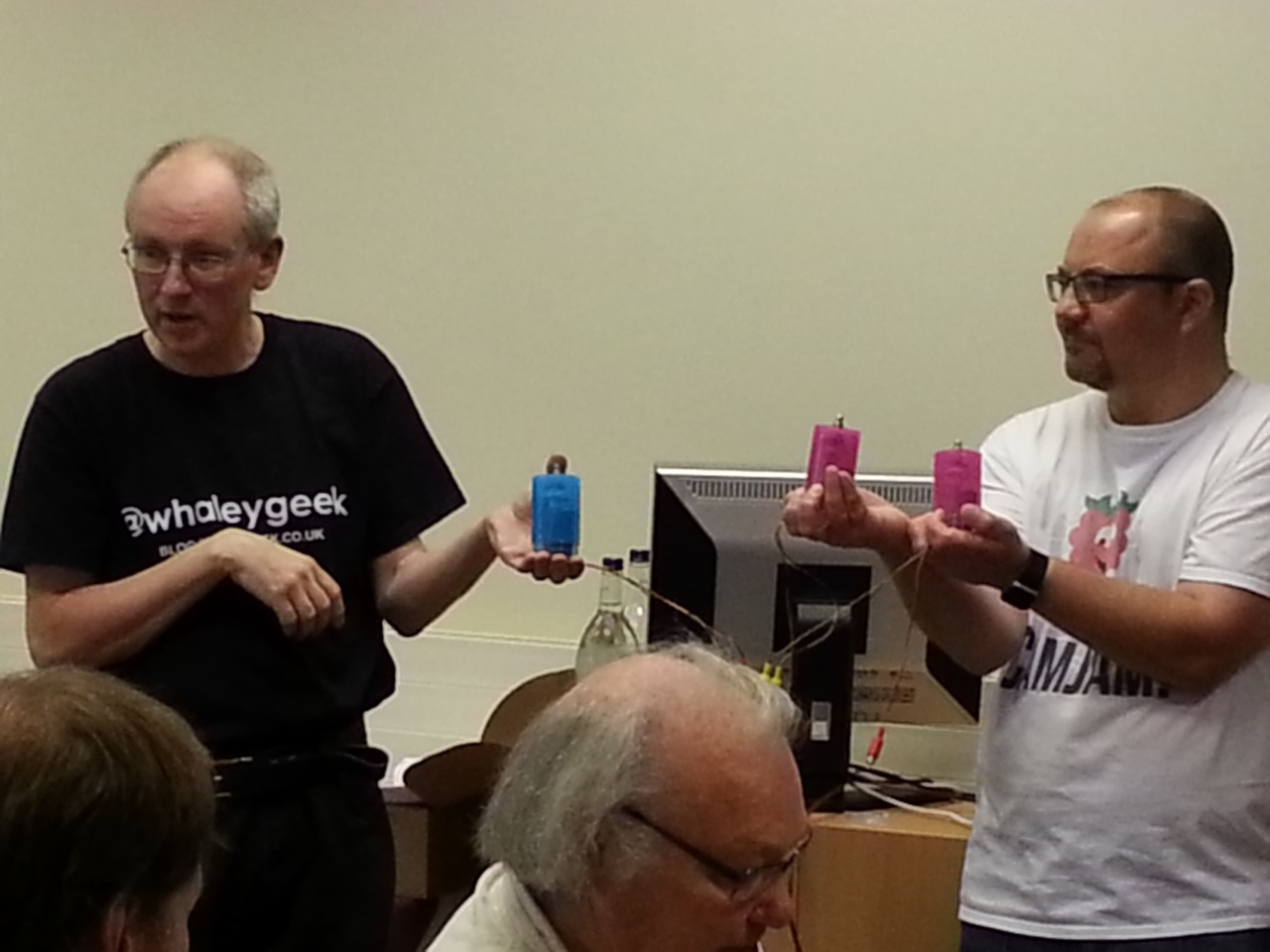
@whalegeek & @geeky_tim demonstrate the “Internet of Things”
OK, so not 100% accurate; a Pi controlled Adafruit Trinket controlled NeoPixel ring 😀
I got the idea from seeing Dave Whale’s serial based Arduino interface with the Pi. The Trinket doesn’t have serial so I had to use something else to talk to it.
Enter I²C; on the Trinket side I’m using the TinyWireS library, on the Pi side I’m calling smBus.writeList() with a list of the bytes I wish to send. You’ll notice in the video there’s an extra breakout in the circuit, this is a bi-directional level converter to allow the 5v Trinket to talk to the 3.3v Pi without releasing any magic smoke.
My aim is to implement the commands in the Neopixel library however at the moment it just calls setPixelColor with the 4 values (LED, Red, Green, Blue) provided by the Pi. I have a special case of LED==0xFF which lights all LEDs the specified colour (a concept I have pinched from David). I have included the code below in it’s current (probably hacky) state.
One problem I did find is that the Pi randomly “loses” the I²C address of the Trinket and reports it as 0x03 for a second or two. I’m not sure if the problem is the Pi or Trinket end but it seems to be an issue with Arduinos in general. The basis of the work around I used in my Python code can be found here. If anyone knows the reason for this I would be most grateful; it’s a horrible hack
importtimeimport smbus
importosimportsubprocess
i2cBus =0
i2cAddr =0x04
bus = smbus.SMBus(i2Bus)
debug =Falsedef writeList(reg,list):
sent =False
attempt =0while sent==False:
if debug:
print"I2C: Writing list to register 0x%02X:" % reg
printlisttry:
bus.write_i2c_block_data(i2cAddr, reg,list)
sent =TrueexceptIOError:
#a 'hack' to catch the Arduino disappearing at random intervals#runs i2cdetect to refresh the i2c interface, output to /dev/null so we don't see the output
FNULL =open(os.devnull,'w')
retcode =subprocess.call(['i2cdetect','-y',str(i2cBus)], stdout=FNULL, stderr=subprocess.STDOUT)time.sleep(0.1)
attempt +=1if attempt ==10:
raiseException('Unable to connect via I2C')def setLED(led, red, green, blue):
bytes=[led, red, green, blue]
writeList(0x01,bytes)
setLED(0xFF,0,0,0)time.sleep(0.5)
setLED(0xFF,32,32,32)time.sleep(0.5)
setLED(0xFF,0,0,0)try:
whileTrue:
for p inrange(0,16):
setLED(p,32,0,0)time.sleep(0.1)for p inrange(0,16):
setLED(p,0,32,0)time.sleep(0.1)for p inrange(0,16):
setLED(p,0,0,32)time.sleep(0.1)for p inrange(0,16):
setLED(p,0,0,0)time.sleep(0.1)exceptKeyboardInterrupt:
pass
setLED(0xFF,0,0,0)
import time
import smbus
import os
import subprocess

i2cBus = 0
i2cAddr = 0x04
bus = smbus.SMBus(i2Bus)
debug = False

def writeList(reg, list):
    sent = False
    attempt = 0
    while sent==False:
        if debug:
            print "I2C: Writing list to register 0x%02X:" % reg
            print list
        try:
            bus.write_i2c_block_data(i2cAddr, reg, list)
            sent = True
        except IOError:
            #a 'hack' to catch the Arduino disappearing at random intervals
            #runs i2cdetect to refresh the i2c interface, output to /dev/null so we don't see the output
            FNULL = open(os.devnull, 'w')
            retcode = subprocess.call(['i2cdetect', '-y', str(i2cBus)], stdout=FNULL, stderr=subprocess.STDOUT)
            time.sleep(0.1)
            attempt += 1
            if attempt == 10:
                raise Exception('Unable to connect via I2C')

def setLED(led, red, green, blue):
    bytes= [led, red, green, blue]
    writeList(0x01, bytes)

setLED(0xFF, 0, 0, 0)
time.sleep(0.5)
setLED(0xFF, 32, 32, 32)
time.sleep(0.5)
setLED(0xFF, 0, 0, 0)

try:
    while True:
        for p in range(0, 16):
            setLED(p, 32, 0, 0)
            time.sleep(0.1)
        for p in range(0, 16):
            setLED(p, 0, 32, 0)
            time.sleep(0.1)
        for p in range(0, 16):
            setLED(p, 0, 0, 32)
            time.sleep(0.1)
        for p in range(0, 16):
            setLED(p, 0, 0, 0)
            time.sleep(0.1)
except KeyboardInterrupt:
        pass

setLED(0xFF, 0, 0, 0)
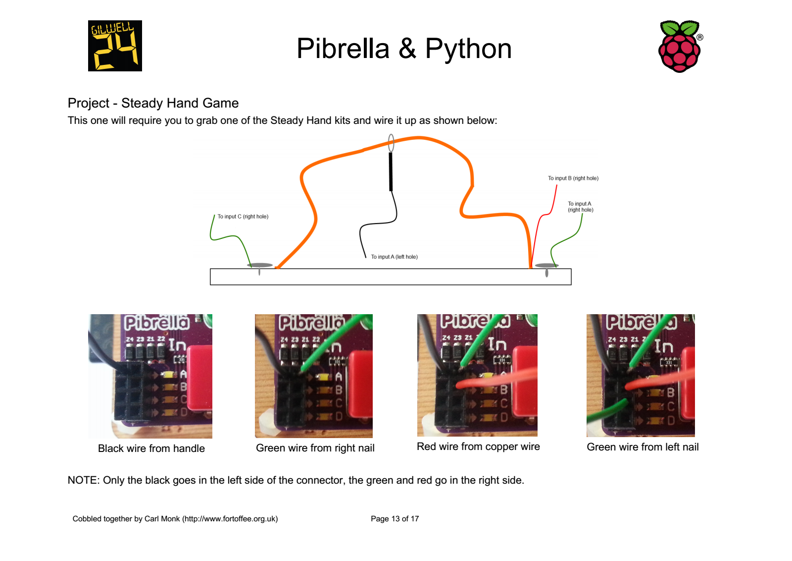
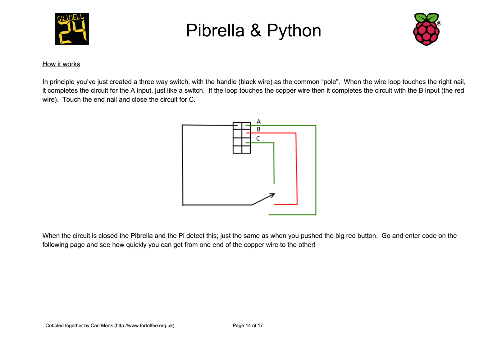
I’m currently writing some Pi activity packs to use at a big Scout event on Saturday. One of them uses the excellent PiBrella to allow easily accessible physical computing via the GPIO interface.
After taking the reader/coder through the basics (lights, buzzer and the big red button!) I put together an extension task to make a Steady Hand/Live Wire game. Here’s the setup and introduction
import pibrella
importtime
state ='end'
startTime =0
endTime =0
touch =0whileTrue:
#start position touchedif pibrella.input.a.read():
if state !='reset':
startTime =0
touch =0
state ='reset'print'Home and reset'#copper wire touchedelif pibrella.input.b.read():
if state =='started':
print'Touch!'
touch +=1
state ='touch'
pibrella.light.on()#end position touchedelif pibrella.input.c.read():
if state =='started':
endTime =time.time()
state ='end'print'You made it in', endTime - startTime,'seconds!'print'You had', touch,'touches of the wire'elifnot pibrella.input.a.read():
# we've startedif state =='reset':
print'Timer started - Good luck!'
state ='started'
touch =0
startTime =time.time()# we've stopped touching the wireelif state =='touch':
state ='started'
pibrella.light.off()time.sleep(0.1)
import pibrella
import time

state = 'end'
startTime = 0
endTime = 0
touch = 0

while True:

    #start position touched
    if pibrella.input.a.read():
        if state != 'reset':
            startTime = 0
            touch = 0
            state = 'reset'
            print 'Home and reset'

    #copper wire touched
    elif pibrella.input.b.read():
        if state == 'started':
            print 'Touch!'
            touch += 1
            state = 'touch'
            pibrella.light.on()

    #end position touched
    elif pibrella.input.c.read():
        if state == 'started':
            endTime = time.time()
            state = 'end'
            print 'You made it in', endTime - startTime, 'seconds!'
            print 'You had', touch, 'touches of the wire'

    elif not pibrella.input.a.read():
        # we've started
        if state == 'reset':
            print 'Timer started - Good luck!'
            state = 'started'
            touch = 0
            startTime = time.time()

        # we've stopped touching the wire
        elif state == 'touch':
            state = 'started'
            pibrella.light.off()

    time.sleep(0.1)
and that’s it. If you saw me at CamJam, the one I had there was a pimped up version. It had an LCD attached to show the fastest time and lives remaining. The buzzer on the Pibrella was also used, while the LEDs counted down your three lives. But those, dear reader, are YOUR extension tasks 🙂
One of my favourite Pibrella projects so far! Built in true maker fashion with scraps and gaffer tape! #camjampic.twitter.com/QJU8714yPI
A couple of weeks ago the lovely Lisa Mather (party planner extraordinaire) put out a request on Twitter for party games. This was for the Manchester Raspberry Jamboree after party on the 28th February (more on the jam in my next post).
So, having already cobbled the basic Snake game together in December I offered to polish it up a bit and add scoring functionality. In addition I felt it needed a better control interface than the keyboard, so a quick shout out to some local friends and I had a Quickshot II+ from a Spectrum ZX81 – it even has the clicky micro switches that any child of the 80’s instantly recognises – mmmmm, retro.
The core code from my last post hasn’t changed much, the main differences are;
swapping keyboard input routine for GPIO pins detection – one for each switch in the joystick (up/down/left/right/fire)
implementing code to record scores (1 point for each piece of food) and using two of the 4x seven segment displays from the Delorean Time Circuit for displaying them
Wiring was a pig (as you can see), but worth it in the end; even if I did have to do some gorilla soldering on Friday when a couple of leads came loose. I highly recommend buying at least the 8×8 grid as a PCB kit (e.g. Pimoroni or CPC) to save your sanity. The desoldering of the seven segments and subsequent wiring you see here took me a goodly portion of my Sunday afternoon 🙁
In the picture you can see 5 (extra chunky) resistors on the breadboard. These are being used to pull the GPIO pins low (or off). As the joystick is moved, the internal switches will complete the circuit with the +3.3v line (red wires) which will set the attached pin high (or on). This is detected by the code and the snake moves the chosen direction (if it’s allowed to of course).
The game had a lot of interest and went down well with young and young at heart. The high score went to both Oliver (who achieved it first) and Michael with a score of 22!
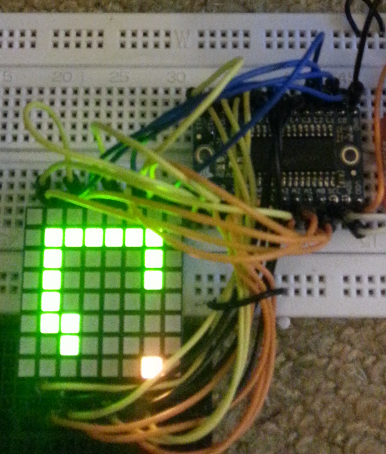
One of the other things the Adafruit LED Backpacks are bundled with is an 8×8 LED matrix. As I no longer needed my Time Circuit project I removed a backpack from the setup and ordered a Red/Green matrix from CPC. I purposely bought the bi colour matrix as the red, green and yellow (r+g) gives me scope to play around more.
So what first? Well, I needed to wire it up; and as I am using the Adafruit Python libraries again I need to make sure the red and green pins were wired according to their code (red = a0 – a7, green = a8 – a15). To make sure everything was in order I ran the example Python code from the library which cycles through each LED in red, green then yellow.
Let’s Code
In my code there are four main variables
snake – a list object containing the x,y coordinates of each piece of the snake at any one time. These are in head to tail order.
food – contains the x,y coordinates of the current ‘food’ block on the display
direction – a string that holds the direction of travel of our snake r(ight), l(eft), u(p) or d(own)
grid – an instance of the Adafruit 8×8 grid library
The main function then has the following actions:
Check for key press; see if we need to change direction
Identify the next square the snake will move to
Check to see if it’s hit the edge or itself
Check to see if we’ve ‘eaten’ the food
Update the snake object to move it on one square
Draw the snake
To manage the snake the list object is used as a queue or First In First Out, aka FIFO, structure (that’s a proper programming term and everything kids!). So every move is done in two steps, insert the new head location into the first position (or push) and remove (or pop) the last item in the queue.
Before the insert happens the new coordinate is checked to see if we need to do anything special.
If the new head is outside the grid (hit the edge) or is the same location as part of the snake body then the code walks the snake list object and turns each coordinate red.
If the snake eats the food then the tail coordinate stays on the queue, extending the body by 1
That’s about it really. The only other thing to note is that without using PyGame and an interactive screen capturing the keys is not quite as straight forward as you would hope. There are two functions keyPress and control that I borrowed from the interwebs (there’s stacks of examples) to capture the key presses on a separate thread so that the main display loop (move snake, redraw etc) doesn’t hang waiting for a key press.