Looking at the Adafruit plans it would take 9 backpacks to achieve the desired effect. Searching around the UK suppliers these were going to cost me £10 a time, plus having to use the 74HC138 as documented in the original design to split the signal to drive all 9, this was going to get expensive! Luckily they have made the driver chip available as a separate breakout board exposing all 8 cathodes and 16 anodes for only £5. Also, as per the 7-segment backpacks, Adafruit provide a python library to get you started.
The Adafruit 7-segment backpacks use common cathode displays, which is logical as the HT16K33 chip has 8x16bit buffers keyed to the 8 cathodes; one per digit (and one for the colon, which leaves 3 spare). Then all the code needs do is write the appropriate 8bit value to a buffer turn on/off the 7 segments and decimal as needed. For example the number 2 looks like this

. g f e d c b a

0 1 0 1 1 0 1 1

= 0x5B
Where a is the top segment and the rest follow clockwise from there (f is top left, g is the middle). Write 0x5B to buffer/cathode 0 and the first digit will show the number 2 as the appropriate anodes will be set high.
One Breakout To Rule Them All
Well, not quite. For this project we’re only interested in the digits on the first two displays (month, day and year), the colon is not needed until the third display as this is where the time is shown, so that’s 12 digits + 1 colon. This is feasible with the common cathode displays, but I ended up buying common anodes (by genius or otherwise – I’ll let you decide). This actually helped me with the coding logic later as we can have one per date/time display. Remember this is only enough for one row; a Delorean Time Circuit has 3 banks of date/time to show, so we will need 3 of these breakouts.

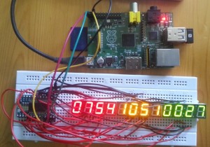
First working circuit showing start time in red, current time in yellow and seconds in green (digits 3 and 4 only) – click to enlarge
Using the common anode 7-segments turns this logic on it head (OK, turns it by 90° if you want to be pedantic) as now each buffer/cathode represents a segment (a-g and decimal) across a possible 16 digits (one per anode). 0x5B written to buffer 0 in our example above would light the top segment on digits 1, 2, 4, 5 and 7 (as buffer 0 now represents all the a segments). We’ll come back to this later as that’s a coding issue.
If you were to use common cathode then the first 8bits of the 16bit buffer could represent digits 1-8 (month, day, year) and the remaining 8bits of the buffers could be used for time and colon. But that’s outside the scope of this write up.